


1
1-4 Genius Modular Redundancy Flexible Triple Modular Redundant (TMR) System
User’s Manual – March 1995
GFK-0787B
Busses and Bus Controllers
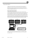
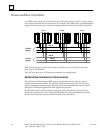
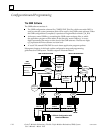
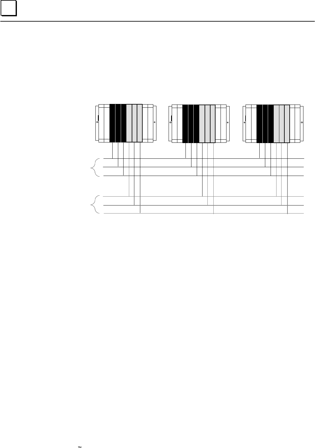
In a GMR system, there can be one to three bus controllers per bus, per PLC. Larger systems
may require more than one I/O subsystem. For example, the GMR system represented below
has two I/O subsystems for a total of six independent Genius busses and 18 bus controllers.
ABCABC
ABCABC ABCABC
Bus A
Bus B
Bus C
Bus A
Bus B
Bus C
PLC A PLC CPLC B
I/O Sub–
system
I/O Sub–
system
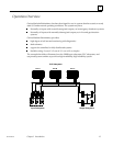
Each Genius bus uses a single twinax cable over distances of up to 7500 feet and data
rates of up to 153.6K baud.
Each PLC may have up to 31 Genius bus controllers, in multiple racks.
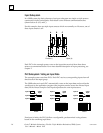
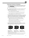
Additional Bus Controllers for Communications
The Genius busses that support GMR input/output groups are also used for internal
communications between PLCs, as explained on the previous page. They should not be
used for datagram communications. Separate busses for communications can be used for
datagrams or additional global data in the application program.
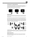
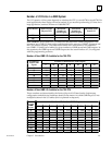
The Bus baud rate should be selected on the basis of the calculations in the Genius I/O
System and Communications User’s Manual (GFK-90486). For correct autotesting in a GMR
system, the Genius bus scan time should not be be more than 60mS.