


7
7-5GFK-0787B Chapter 7 Programming Information
Input and Output Addressing for GMR
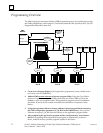
I/O addressing for GMR is unlike a that of conventional Series 90-70 application. In a
conventional application, input and output addresses are assigned sequentially, starting at the
beginning of the Input Table and Output Table. In a GMR application, the GMR software
automatically divides the Discrete Input and Output Tables and the Analog Input Table into
special-purpose areas.
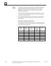
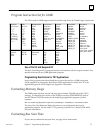
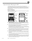
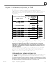
Discrete I/O Addressing
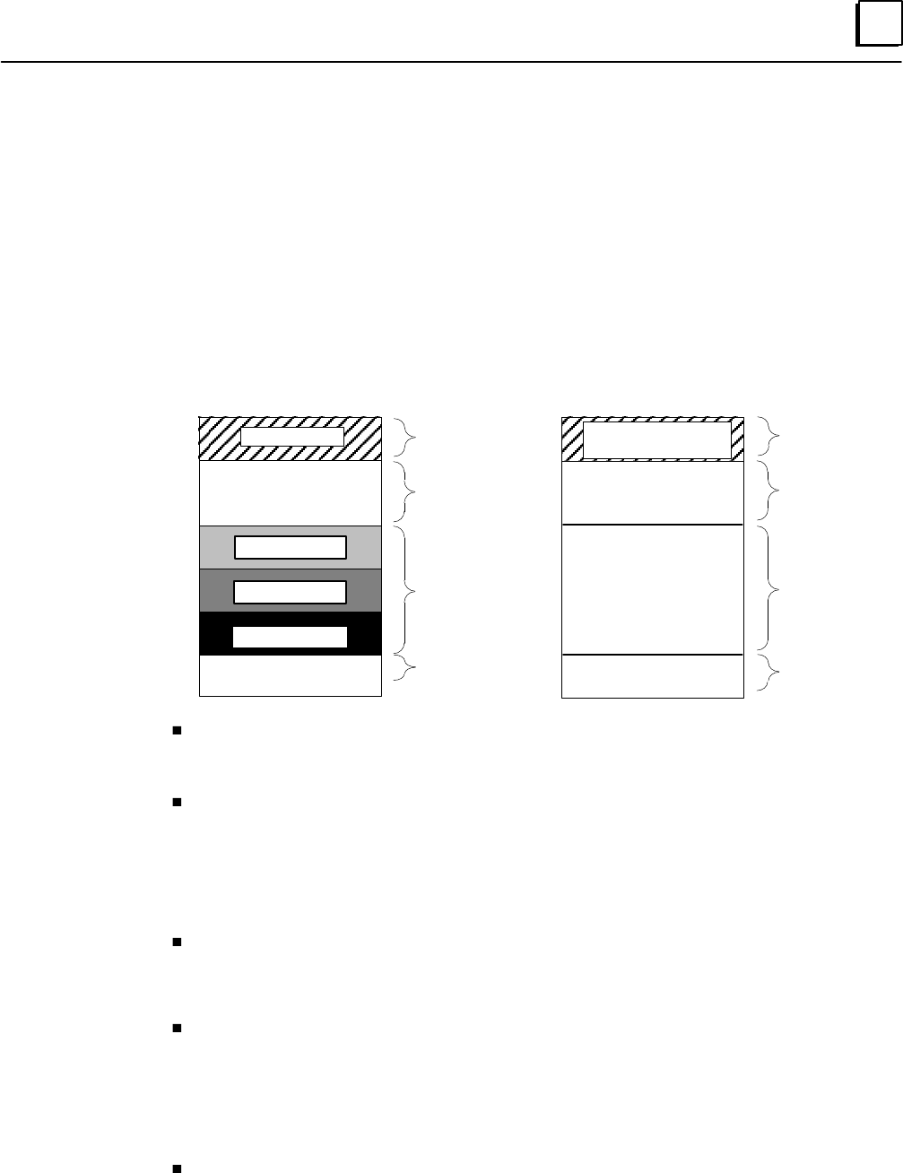
The discrete Input Table and Output Table are divided up into separate areas for redundant
and non-voted data, as shown below.
Discrete Input Table
Voted Inputs
Available for
non-voted Inputs
Bus A inputs
Bus B inputs
Bus C inputs
Reserved inputs
Discrete Output Table
Logical Redundant
Outputs
Available for
non-voted Outputs
Physical Redundant
Outputs
Reserved memory
%I0001
%I1024 or %I12288 %Q1024 or %Q12288
%Q0001
non-voted
I/O
Inputs to PLC
Bus A, B, C
Inputs
Reserved
non-voted
I/O
Outputs from
PLC
Reserved
Output
Memory
Reserved,
Outputs to
Blocks
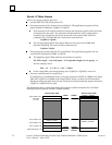
Voted inputs and logical redundant outputs occupy the beginning of the discrete I/O
tables. Normally, the application program utilizes these inputs and outputs, although it
can also access the rest of the I/O table data if necessary.
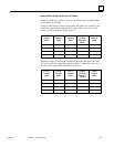
Non-voted inputs and outputs occupy the next portions of the Input and Output Tables.
These are the inputs and outputs of blocks that are present in the system either as
non-voted blocks on GMR busses, or on other busses.
The starting address for non-voted data depends on the amount of redundant data, as
explained above. In the same example, if there were 64 voted inputs and 48 logic outputs,
non-voted I/O data would begin at addresses %I0065 and %Q049.
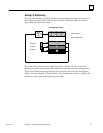
The area of Output Table memory that corresponds to the bus A, B, and C input data in
the Input Table is reserved. The reason this area is reserved is that input blocks used in
redundancy are configured as combination input/output blocks. So the corresponding
output references should not be used for other purposes.
The last part of the Output Table is used for the copied physical redundant output data.
This is the data that is actually sent to the Genius blocks that are included in the GMR
configuration.
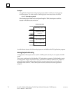
The same amount of memory is reserved in the corresponding area of the Input Table. It
is used to allow GMR fault processing to be inhibited on a circuit-by-circuit basis for the
corresponding physical redundant outputs.
The total amount of I/O data available depends on the CPU type. For the model 788 CPU,
there can be a total of 352 physical inputs and outputs or approximately 100 redundant
I/O points. For the model 789, there can be a total of 12288 physical inputs and outputs
(or a maximum of 4096 redundant I/O points).