


6
6-36 Genius Modular Redundancy Flexible Triple Modular Redundant (TMR) System
User’s Manual – March 1995
GFK-0787B
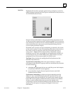
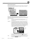
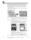
Threshold Discrepancy: Specify by what percent an individual input
for the channel may deviate from the voted input value. During
operation, if any of the corresponding physical inputs deviates from the
voted input value by more than this amount (in either direction), it will
generate a fault that must be cleared by the application program.
For example, if the physical inputs for a channel were 91, 100, and 111
degrees, the voted input value would be 100 degrees. If the Discrepancy
Threshold for the channel had been configured as 10%, the input
reporting 111 degrees would be outside the acceptable range.
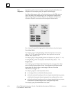
Limit Discrepancy: Similarly, specify by what percent an individual input
for the channel may deviate from the full scale deflection of the channel
(represented by the entries maximum and minimum value). During
operation, if any of the corresponding physical inputs deviates by more
than this amount (in either direction) from the voted input value, it will
generate a fault that must be cleared by the application program.
For example, if the physical inputs for a channel were 9, 10, and 15, and
the full scale deflection were configured at 200, with a limit discrepancy
of 10%, the voted input would be 10 and all three inputs would be
within the discrepancy limit (of 20), and no fault would be reported.
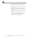
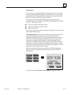
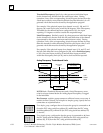
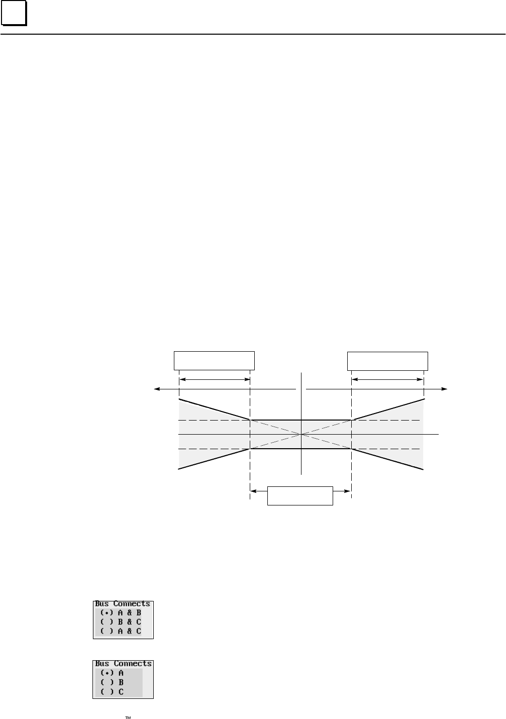
Analog Discrepancy Thresholds and Limits
%AI
Voted
Input
Limit Discrepancy
% of FSD
PositiveNegative
Threshold Discrepancy
% of Reading
Threshold Discrepancy
% of Reading
Discrepancy
Value
NOTE: Both a Threshold Discrepancy and a Limit Discrepancy must
exist for a input channel before an Analog Input Discrepancy is logged
in the fault table.
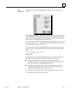
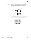
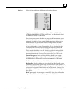
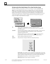
Bus Connects: a triplex group connects to all three busses, so no entry is
needed for Bus Connects. For a duplex or simplex group, specify the bus
connections as explained below.
For a duplex group, configure the two busses the group is connected to: A
(from the PLC using serial bus address 31) and B (from the PLC using
serial bus address 30), or B and C (the PLC using serial bus address 29)
or A and C.
For a simplex group, configure the bus the group is connected to: A (from
the PLC using serial bus address 31), B (from the PLC using serial bus
address 30), or C (from the PLC using serial bus address 29).