


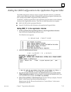
7
7-25GFK-0787B Chapter 7 Programming Information
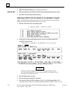
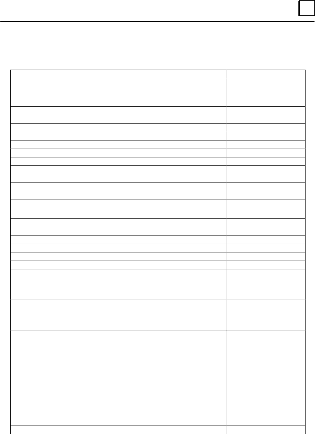
Data Table Numbers
Table Contains Range for Start Value Range for End Value
11 Digital Input Discrepancy faults Greater than or equal to the
first digital input address for A,
B, or C.
Less than the start plus the
maximum digital input ad-
dress for A, B, or C.
14 Digital Input Autotest faults start>=1 end<=12228, end<=start
15 Digital Input Genius faults start>=1 end<=12228, end<=start
16 Digital Input Point faults start>=1 end<=12228, end<=start
21 Digital Output Discrepancy faults: PLC A start>=1 end<=12228, end<=start
22 Digital Output Discrepancy faults: PLC B start>=1 end<=12228, end<=start
23 Digital Output Discrepancy faults: PLC C start>=1 end<=12228, end<=start
24 Digital Output Autotest faults start>=1 end<=12228, end<=start
25 Digital Output Genius faults start>=1 end<=12228, end<=start
26 Digital Output Point faults start>=1 end<=12228, end<=start
27 Digital Logon faults (PLC A) First group number required Last group number required
28 Digital Logon faults (PLC B) First group number required Last group number required
29 Digital Logon faults (PLC C) First group number required Last group number required
31 Analog Input Discrepancy faults Greater than or equal to the
first digital input address for A,
B, or C.
Less than the start plus the
maximum digital input ad-
dress for A, B, or C.
35 Analog Input Genius faults start>=1 end<=8192, end<=start
36 Analog Input Point faults start>=1 end<=8192, end>=start
37 Analog Input Low Alarms start>=1 end<=8192, end>=start
38 Analog Input High Alarms start>=1 end<=8192, end>=start
45 Analog Output Genius faults start>=1 end<=8192, end>=start
46 Analog Output Point faults start>=1 end<=8192, end>=start
47 Input shutdown timers (per block)
Returns a single word indicating the shutdown
timer value as seconds of elapsed time. A value
of –1 means a fault exists but the timer has not
started (the Shutdown Cancel bit is On).
High byte contains rack num-
ber (0–7) and low byte con-
tains slot number (1–9)
High byte contains the number
1. Low byte contains the Serial
Bus Address (SBA) of the de-
sired block you want shut-
down information from (0–28)
48 Output shutdown timers (per block)
Returns a single word indicating the shutdown
timer value as seconds of elapsed time. A value
of –1 means a fault exists but the timer has not
started (the Shutdown Cancel bit is On).
High byte contains rack num-
ber (0–7) and low byte con-
tains slot number (1–9)
High byte contains the number
1. Low byte contains the Serial
Bus Address (SBA) of the de-
sired block you want shut-
down information from (0–28)
49 Input shutdown timers (per GBC)
For each SBA, returns a word indicating the
shutdown timer value as seconds of elapsed
time. A value of –1 means a fault exists but the
timer has not started (the Shutdown Cancel bit
is On). A value of 0 means a block does not exist
or has no associated shutdown timer. All output
blocks return the value 0.
High byte contains rack num-
ber (0–7) and low byte con-
tains slot number (1–9) where
the desired Bus Controller is
located.
unused
50 Output shutdown timers (per GBC)
For each SBA, returns a word indicating the
shutdown timer value as seconds of elapsed
time. A value of –1 means a fault exists but the
timer has not started (the Shutdown Cancel bit
is On). A value of 0 means a block does not exist
or has no associated shutdown timer. All input
blocks return the value 0.
High byte contains rack num-
ber (0–7) and low byte con-
tains slot number (1–9) where
the desired Bus Controller is
located.
unused
1000h Configuration text description unused unused