


3
3-6 Genius Modular Redundancy Flexible Triple Modular Redundant (TMR) System
User’s Manual – March 1995
GFK-0787B
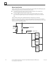
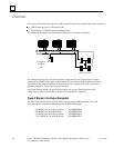
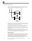
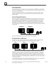
4-Block Output Groups
All four blocks in a group must be either 16-circuit or 32-circuit blocks. In a group, two
source-type Genius blocks are connected in parallel on one side of each load, and two
sink-type Genius blocks are connected in parallel on the other side.
Load
Source Blocks
(IC660BBD020
or
IC660BBD024)
Sink Blocks
(IC660BBD022
or
IC660BBD025)
Bus A
Bus B
Bus C
A
B
CD
There are three busses. One source block and one sink block are connected to either bus
A or bus B (see blocks B and D on bus B in the illustration above). The other two blocks
are connected to the remaining two busses (A and C above).
The illustration shows just one load for a group of four blocks. However, up to 16 loads
could be controlled by the same group of four blocks (using 16-circuit blocks).
When the blocks are configured, each is assigned the same output reference addresses
using Logicmaster 90. Then, the blocks are configured for GMR mode using the Genius
Hand-held Monitor.
Output circuits that are to be autotested must be able to withstand the On and Off pulse
times used by the test. Check each output device’s characteristics against the
specifications listed on page 8-12 (for 16-point blocks) and page 8-17 (for 32-point blocks)
to verify that it can be autotested and/or used in a 4-block output group.
Output Load Sharing
In a 4-block output group, current to output loads is shared. Therefore, it is not possible
to be sure exactly how much power is being provided by each block. If 16-circuit blocks
in a GMR output group are configured for No Load fault reporting, the minimum
connected load that can be used is 100mA. If blocks in a 4-block output group are
configured for No Load reporting, a system output No Load fault will only be reported if
both of the source blocks or both of the sink blocks report No Load faults.