


246
S:\HP83206A\USRGUIDE\MANUAL\connect.fm
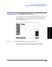
Chapter 8, Connector Descriptions
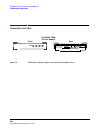
Front Panel Connectors
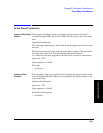
Analyzer Trigger In This connector allows external signals to trigger the Digital Analyzer to begin
sampling the selected input. (Not in use at this time)
Operating Considerations
Used for frame synchronization of the analyzer.
Input impedance = 100 k
Ω
Input level = TTL (rising edge)
Generator
Baseband Data In
This connector allows you to send external data to the Pre-modulation filter/IQ
modulator. (Not in use at this time)
Operating considerations
When using an external reference, the same reference used to generate the
Baseband data must also be connected to the Cellular Adapter’s Ref In connector
to correctly clock the data.
Modulation data consists of two-bit symbols (00, 01, 10, 11) that are sent to the
Pre-modulation filter. The first bit of a symbol is clocked in on the rising edge of
the symbol clock. Care must be taken to properly align the input data with the
Symbol Clock to correctly modulate the Digital Generator.
This signal is not affected by the
Data Delay field setting. The nominal delay
from the first data bit in a two-bit symbol to its peak RF response (decision point)
after pi/4 DQPSK modulation is 12 bits (6 symbols).
Input level = TTL
Data rate = 48.6 kbits/sec
Input impedance = 100 k
Ω