


44
S:\HP83206A\USRGUIDE\MANUAL\getstart.fm
Chapter 1, Getting Started
About the PCS Interface
Using the PCS
Interface
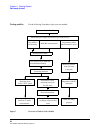
After installing the PCS Interface and successfully running the System
Connectivity test software, you need to perform some additional operations to
properly use the interface. These operations include:
1. Initializing the PCS Interface for operation with the Test System.
2. Entering path losses into the PCS Interface.
3. Specifying the type of mobile your are testing.
4. Compensating for temperature changes.
5. Selecting the correct vocoder.
Initializing the PCS Interface
This must be done every time you turn the instruments on, even if you are not
testing PCS mobiles.
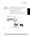
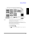
The
PCS Mode field on the CONFIGURE screen initializes the PCS Interface and
tells the Test Set to alter its frequency and power settings accordingly. The
CONFIGURE screen is accessed by pressing SHIFT, DUPLEX (CONFIGURE).
See Figure 8 on page 1 45
DO NOT USE AUTO-
TUNING WITH THE
PCS INTERFACE
When the
PCS Mode
is set to
On
, the RF Analyzer’s
Tune Mode
field is automatically
set to
Manual
. You should not change this setting back to
Auto
while using the PCS
Interface because the automatic tuning function may not properly tune to the down-
converted signal from the interface.
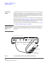
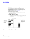
Entering Path Losses to the PCS Interface’s RF IN/OUT port.
Losses from cables and connectors between the mobile being tested and the PCS
Interface’s RF IN/OUT port need to be accounted for. The loss value is entered in
the
PCS RF I/O field on the CONFIGURE screen. Setting the
RF Level Offset field to On allows this value to affect Test Set operation.This
causes the levels in and out of the interface to be compensated for, increasing
measurement accuracy. See Figure 8 on page 1 45.