


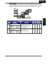
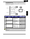
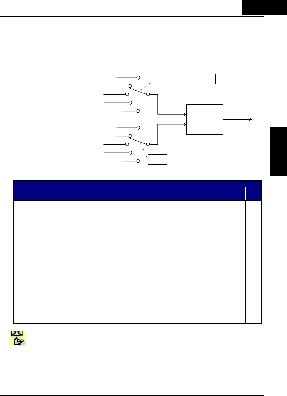
Analog Input Calculate Function – The inverter can mathematically combine two input
sources into one value. The Calculate function can either add, subtract, or multiply the
two selected sources. This provides the flexibility needed by various applications. You
can use the result for the output frequency setting (use A001=10) or for the PID Process
Variable (PV) input (use A075=03).
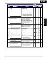
“A” Function Defaults
Func.
Code
Name /
SRW Display
Description
Run
Mode
Edit
-FE
(EU)
-FU
(USA)
Units
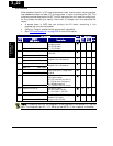
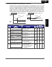
A input select for calculate
function
A141
CALC Slct1 POT
Five options:
00…Digital operator
01…Keypad potentiometer
02…[O] input
03…[OI] input
04…Network variable
U
01 01
−
B input select for calculate
function
A142
CALC Slct2 OI
Five options:
00…Digital operator
01…Keypad potentiometer
02…[O] input
03…[OI] input
04…Network variable
U
02 02
−
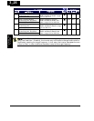
Calculation symbolA143
CALC SMBL
Calculates a value based on the A
input source (A141 selects) and B
input source (A142 selects).
Three options:
00…ADD (A input + B input)
01…SUB (A input - B input)
02…MUL (A input * B input)
U
00 00
−
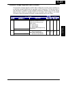
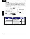
NOTE: For A141 and A142, it is not possible that you use [O] and [OI] together in
calculation, because it is not allowed to use the both inputs at the same time on X200
series inverter.
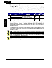
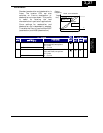
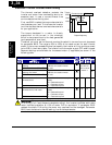
Digital operator
Potentiometer
[O] input
[OI] input
Network variable
A141
A
input select
A142
B input select
• A + B
• A - B
• A * B
A
B
A143
Digital operator
Potentiometer
[O] input
[OI] input
Network variable
“CAL”
(result)
3
−
29
Configuring Drive
Parameters