


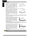
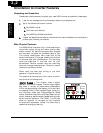
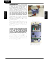
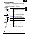
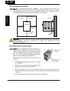
DIP Switch Introduction
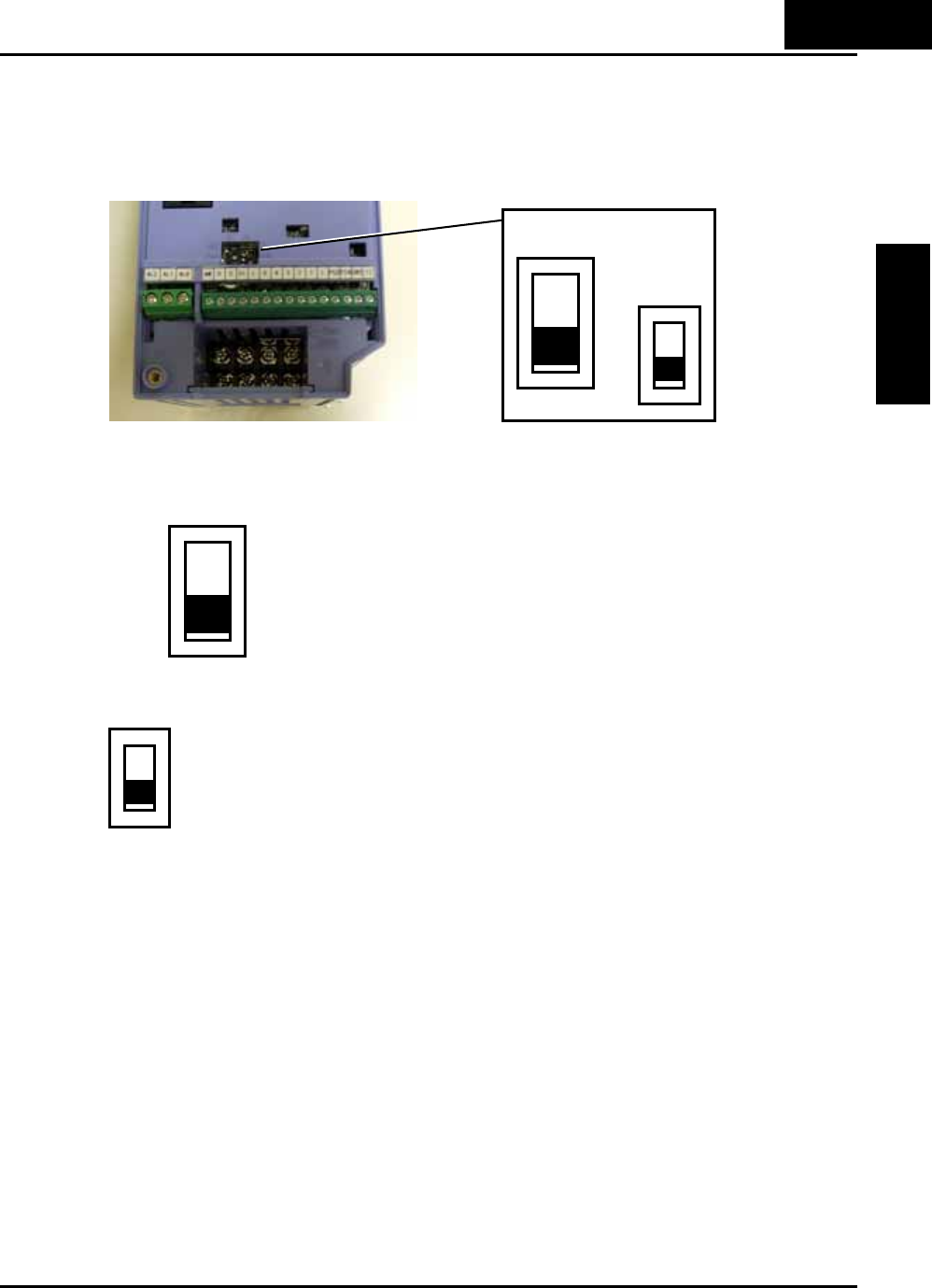
The inverter has internal DIP switches, located at the middle of the logic connectors as
shown below. This selection provides an introduction, and refers you to other chapter
that discuss the DIP switch in depth.
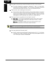
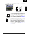
The 485/OPE (RS485/Operator) DIP switch configures the
inverter’s RS485 serial port. You can use either the inverter’s
integrated keypad or the OPE (OPE SR-mini) connected via a
cable to the serial port. In this case the SW7 should be set OPE
(default set). Inverter control via a ModBus network
communication requires the “485” setting. See “Connecting the
Inverter to ModBus” on page B-3 for more details.
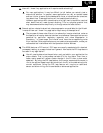
The SW8 is for the emergency signal input. If you turn this DIP
switch ON, the inverter is ready to receive emergency signal
from the dedicated terminal #3. Inverter shuts off the output by
means of pure hardware when a signal is given to the terminal.
It complies to EN954-1, category 3. Each signals related to this
emergency input must be in accordance with the norm.
Additionally, the logic input terminal assign will be changed
automatically if the SW8 is made ON. See “Safe Stop” on page
4-32 for more details.
2
−
5
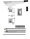
Inverter Mounting
and installation
SW7
SW8
485
OPE
ON
OFF
SW7
485
OPE
SW8
ON
OFF