


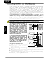
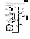
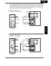
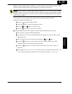
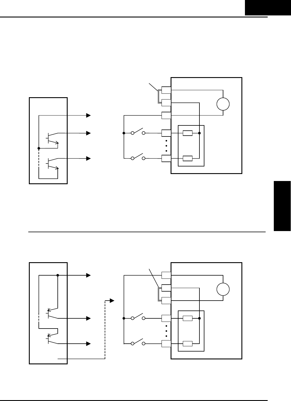
The two diagrams below input wiring circuits using the inverter’s internal +24V supply.
Each diagram shows the connection for simple switches, or for a field device with
transistor outputs. Note that in the lower diagram, it is necessary to connect terminal
[L] only when using the field device with transistors. Be sure to use the correct
connection of the short bar shown for each wiring diagram.
Sinking Inputs, Internal Supply
Short bar = [PLC] – [P24] position
GND
5
1
Field device
Open collector outputs,
NPN transistors
X200
P24
1
5
24V
PLC
Input
circuits
+
-
Logic GND
Input common
Short bar
Input switches
L
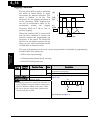
Sourcing Inputs, Internal Supply
Short bar = [PLC] – [L] position
Common to
[P24]
5
1
Field device
PNP transistor
sousing outputs
X200
P24
1
5
24V
PLC
Input
circuits
+
-
Logic GND
Input common
Short bar
Input switches
L
GND
to PNP bias
circuits
4
−
9
Operations and
Monitoring