


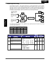
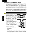
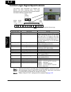
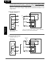
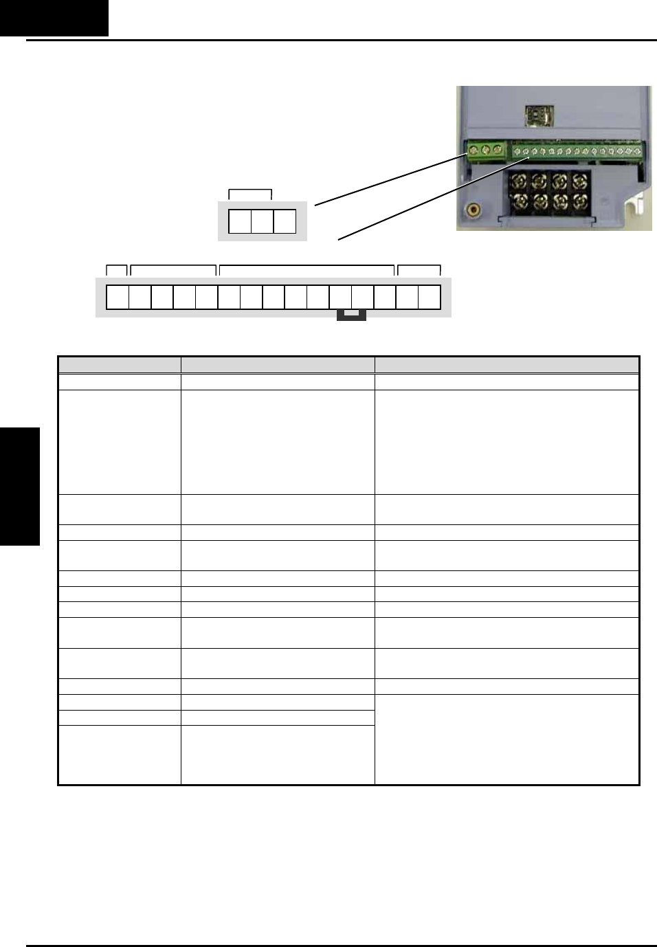
Control Logic Signal Specifications
The control logic connectors are located just
behind the front housing cover. The relay
contacts are just to the left of the logic connectors.
Connector labeling is shown below.
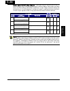
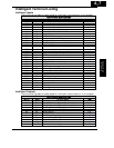
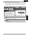
Terminal Name Description Ratings
[P24] +24V for logic inputs 24VDC, 30mA. (do not short to terminal L)
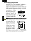
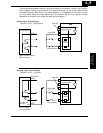
[PLC] Intelligent input common Factory set: Source type for –FE and –HE
models (connecting [P24] to [1]~[5] makes
each input ON). To change to sink type,
remove the short wire between [PLC] and
[L], and connect it between [P24] and [L]. In
this case, connecting [L] to [1]~[5] makes
each input ON.
[1], [2], [3], [4], [5] Discrete logic inputs 27VDC max. (use PLC or an external
supply referenced to terminal L)
[L] (right) *1 GND for logic inputs Sum of input [1]~[5] currents (return)
[11] Discrete logic output 50mA max. ON state current,
27 VDC max. OFF state voltage
[CM2] GND for logic output 100 mA: [11] current return
[AM] Analog voltage output 0~10VDC 1mA maximum
[L] (left) *2 GND for analog signals Sum of [OI], [O], and [H] currents (return)
[OI] Analog input, current 4 to 19.6 mA range, 20 mA nominal,
input impedance 250 Ω
[O] Analog input, voltage 0 to 9.8 VDC range, 10 VDC nominal,
input impedance 10 kΩ
[H] +10V analog reference 10VDC nominal, 10mA max.
[AL0] Relay common contact
[AL1] *3 Relay contact, normally open
[AL2] *3 Relay contact, normally closed
250VAC, 2.5A (R load) max.
250VAC, 0.2A (I load, P.F.=0.4) max.
100VAC, 10mA min.
30VDC, 3.0A (R load) max.
30VDC, 0.7A (I load, P.F.=0.4) max.
5VDC, 100mA min.
Note 1: The two terminals [L] are electrically connected together inside the inverter.
Note 2: We recommend using [L] logic GND (to the right) for logic input circuits and
[L] analog GND (to the left) for analog I/O circuits.
Note 3: Default relay N.O./N.C. configuration is reversed. See page 4-35.
4−6
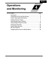
Operations and
Monitoring
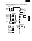
AL2 AL1 AL0
Relay
contacts
AM H O OI L 5 4 3 2 1 L
PLC P24 CM2
11
A
nalog
out
p
ut
A
nalog
in
p
uts
Lo
g
ic in
p
uts
Logic
out
p
ut
Short bar : default
p
osition
(
Source lo
g
ic
)