


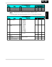
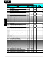
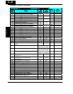

Intelligent Terminal Functions
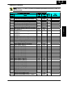
“C” Group Parameters Default Setting
Func.
Code
Name
-FE
(EU)
-FU
(USA)
B031
=10
User
Setting
C001 Terminal [1] function 00 00
U
C201 Terminal [1] function, 2nd motor 00 00
U
C002 Terminal [2] function 01 01
U
C202 Terminal [2] function, 2nd motor 01 01
U
C003 Terminal [3] function 02 16
U
C203 Terminal [3] function, 2nd motor 02 16
U
C004 Terminal [4] function 03 13
U
C204 Terminal [4] function, 2nd motor 03 13
U
C005 Terminal [5] function 18 18
U
C205 Terminal [5] function, 2nd motor 18 18
U
C011 Terminal [1] active state 00 00
U
C012 Terminal [2] active state 00 00
U
C013 Terminal [3] active state 00 00
U
C014 Terminal [4] active state 00 01
U
C015 Terminal [5] active state 00 00
U
C021 Terminal [11] function 01 01
U
C026 Alarm relay terminal function 05 05
U
C028 [AM] signal selection 00 00
9
C031 Terminal [11] active state 00 00
U
C036 Alarm relay active state 01 01
U
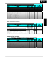
C038 Output mode of low load detection
signal
01 01
9
C039 Low load detection level
Rated current for
each inverter model
9
C041 Overload level setting
Rated current for
each inverter model
9
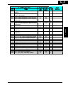
C241 Overload level setting, 2nd motor
Rated current for
each inverter model
9
C042 Frequency arrival setting for
acceleration
0.0 0.0
9
C043 Frequency arrival setting for
deceleration
0.0 0.0
9
C044 PID deviation level setting 3.0 3.0
9
C052 PID FBV function high limit 100.0 100.0
9
C053 PID FBV function variable low limit 0.0 0.0
9
C070 Selection of OPE / ModBus 02 02
9
C071 Communication speed selection 06 04
9
C072 Node allocation 1. 1.
9
C074 Communication parity selection 00 00
9
C075 Communication stop bit selection 1 1
9
C076 Communication error select 02 02
9
C077 Communication error time-out 0.00 0.00
9
C078 Communication wait time 0. 0.
9
C081 O input span calibration 100.0 100.0
9
C082 OI input span calibration 100.0 100.0
9
C−8
Appendix C