


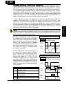
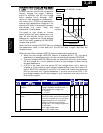
“C” Group: Intelligent Terminal Functions
The five input terminals [1], [2], [3], [4], and [5] can be configured for any of 31 different
functions. The next two tables show how to configure the five terminals. The inputs are
logical, in that they are either OFF or ON. We define these states as OFF=0, and ON=1.
The inverter comes with default options for the five terminals. These settings are
initially unique, each one having its own setting. Note that European and US versions
have different default settings. You can use any option on any terminal, and even use
the same option twice to create a logical OR (though usually not required).
NOTE: Terminal [5] has the ability to be a logical input, and to be an analog input for a
thermistor device when PTC function (option code 19) is assigned to that terminal.
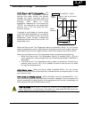
Input Terminal Configuration
Functions and Options – The
function codes
in the following table let you assign one of
twenty eight options to any of the five logic inputs for the X200 inverters. The functions
C001 through C005 configure the terminals [1] through [5] respectively. The “value” of
these particular parameters is not a scalar value, but it is a discrete number that selects
one option from many available
options
.
For example, if you set function C001=00, you have assigned option 00 (Forward Run) to
terminal [1]. The option codes and the specifics of how each one works are in Chapter 4.
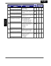
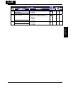
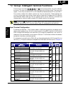
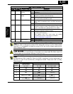
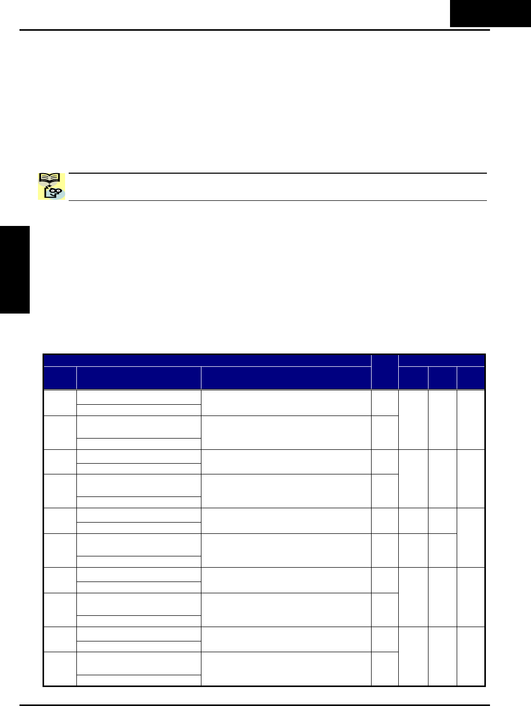
“C” Function Defaults
Func.
Code
Name /
SRW Display
Description
Run
Mode
Edit
-FE
(EU)
-FU
(USA)
Units
Terminal [1] functionC001
IN-TM 1 FW
Select input terminal [1] function, 30
options(see next section)
U
Terminal [1] function,
2nd motor
C201
2IN-TM 1 FW
Select input terminal [1] function for
2nd motor, 30 options(see next
section)
U
00
[FW]
00
[FW]
−
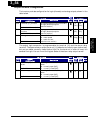
Terminal [2] functionC002
IN-TM 2 RV
Select input terminal [2] function, 30
options(see next section)
U
Terminal [2] function,
2nd motor
C202
2IN-TM 2 RV
Select input terminal [2] function for
2nd motor, 30 options(see next
section)
U
01
[RV]
01
[RV]
−
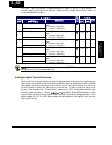
Terminal [3] functionC003
IN-TM 3 AT
Select input terminal [3] function, 30
options(see next section)
U
02
[CF1]
16
[AT]
Terminal [3] function,
2nd motor
C203
2IN-TM 3 AT
Select input terminal [3] function for
2nd motor, 30 options(see next
section)
U
02
[CF1]
16
[AT]
−
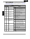
Terminal [4] functionC004
IN-TM 4 USP
Select input terminal [4] function, 30
options(see next section)
U
Terminal [4] function,
2nd motor
C204
2IN-TM 2 USP
Select input terminal [4] function for
2nd motor, 30 options(see next
section)
U
03
[CF2]
13
[USP]
−
Terminal [5] functionC005
IN-TM 5 2CH
Select input terminal [5] function, 30
options(see next section)
U
Terminal [5] function,
2nd motor
C205
IN-TM 5 2CH
Select input terminal [5] function for
2nd motor, 30 options(see next
section)
U
18
[RS]
18
[RS]
−
3
−
49
Configuring Drive
Parameters