


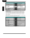
Operational Modes
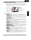
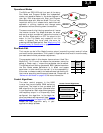
The RUN and PRG LEDs tell just part of the story;
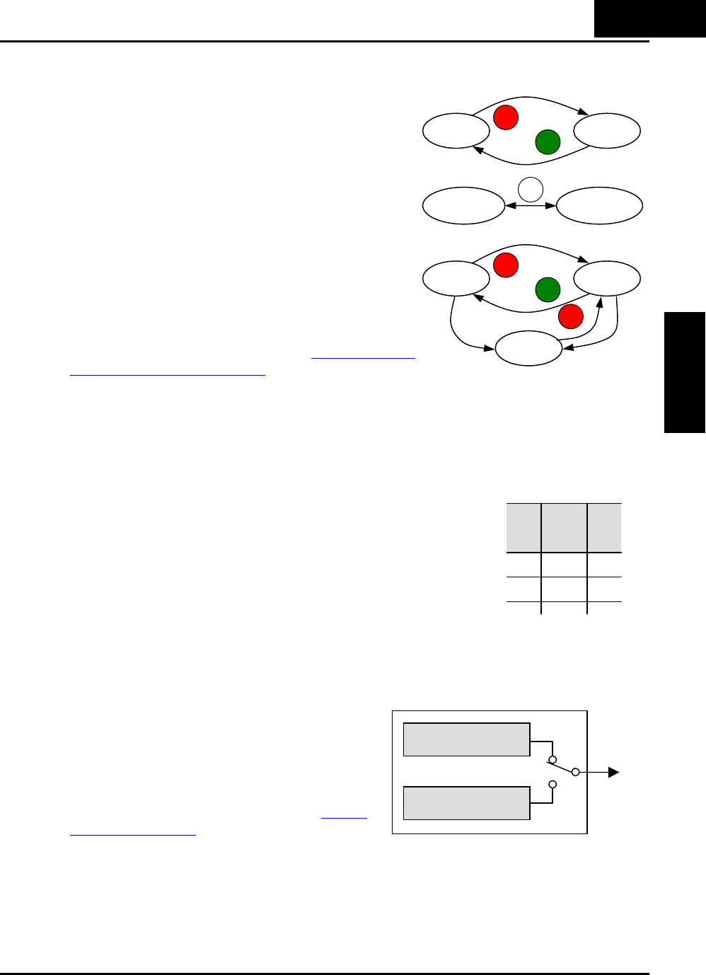
Run Mode and Program Modes are independent
modes, not opposite modes. In the state diagram to
the right, Run alternates with Stop, and Program
Mode alternates with Monitor Mode. This is a very
important ability, for it shows that a technician can
approach a running machine and change some
parameters without shutting down the machine.
The occurrence of a fault during operation will cause
the inverter to enter Trip Mode as shown. An event
such as an output overload will cause the inverter to
exit the Run Mode and turn OFF its output to the
motor. In the Trip Mode, any request to run the
motor is ignored. You must clear the error by
pressing the Stop/Reset switch. See “Monitoring Trip
Events, History, & Conditions” on page 6-5.
Run Mode Edit
The inverter can be in Run Mode (inverter output is controlling motor) and still allow
you to edit certain parameters. This is useful in applications that must run continuously,
you need some inverter parameter adjustment.
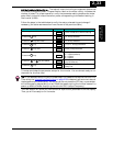
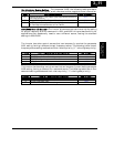
The parameter table in this chapter have a column titled “Run
Mode Edit”. An Ex mark
U means the parameter cannot be
edited; a Check mark
9 means the parameter can be edited.
The Software Lock Setting (parameter B031) determines when
the Run Mode access permission is in effect and access
permission in other conditions, as well. It is the responsibility
of the user to choose a useful and safe software lock setting for
the inverter operating conditions and personnel. Please refer to
“Software Lock Mode” on page 3-36 for more information.
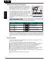
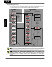
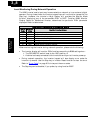
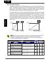
Control Algorithms
The motor control program in the X200
inverter has two sinusoidal PWM switching
algorithms. The intent is that you select the
best algorithm for the motor characteristics
in your application. Both algorithms generate
the frequency output in a unique way. Once
configured, the algorithm is the basis for
other parameter settings as well (see “Torque
Control Algorithms” on page 3-16). Therefore,
choose the best algorithm early in your
application design process.
Run Stop
RUN
STOP
RESET
Monitor Program
FUNC
Run Stop
RUN
STOP
RESET
Trip
STOP
RESET
Fault
Fault
Run
Mode
Edit
U
9
Variable freq. control,
constant torque
Variable freq. control,
reduced torque
Output
Inverter Control Algorithms
3
−
5
Configuring Drive
Parameters