


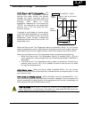
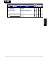
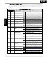
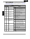
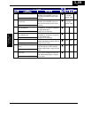

Output Function Summary Table – This table shows all twelve functions for the logical
outputs (terminals [11] and [AL]) at a glance. Detailed descriptions of these functions,
related parameters and settings, and example wiring diagrams are in “Using Intelligent
Output Terminals” on page 4-34.
Output Function Summary Table
Option
Code
Terminal
Symbol
Function Name Description
ON When the inverter is in Run Mode00 RUN Run Signal
OFF When the inverter is in Stop Mode
ON When output to motor is at the set frequency01 FA1 Frequency Arrival Type
1–Constant Speed
OFF When output to motor is OFF, or in any
acceleration or deceleration ramp
ON When output to motor is at or above the set
frequency, even if in accel. or decel rams
02 FA2 Frequency Arrival Type
2–Over frequency
OFF When output to motor is OFF, or at a level
below the set frequency
ON When output current is more than the set
threshold for the overload signal
03 OL Overload Advance
Notice Signal
OFF When output current is less than the set
threshold for the deviation signal
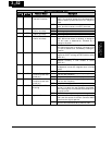
ON When PID error is more than the set threshold
for the deviation signal
04 OD Output Deviation for
PID Control
OFF When PID error is less than the set threshold
for the deviation signal
ON When an alarm signal has occurred and has not
been cleared
05 AL Alarm Signal
OFF When no alarm has occurred since the last
cleaning of alarm(s)
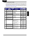
ON When the [O] input value < B082 setting (signal
loss detected), or the [OI] input current < 4mA
06 Dc Analog Input
Disconnect Detect
OFF When no signal loss is detected
ON Transitions to ON when the inverter is in RUN
Mode and the PID Process Variable (PV) is less
than the Feedback Low Limit (C053)
07 FBV PID Second Stage
Output
OFF Transitions to OFF when the PID Process
Variable (PV) exceeds the PID High Limit
(C052), and transitions to OFF when the
inverter goes from Run Mode to Stop Mode
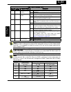
ON When the communications watchdog timer
(period specified by C077) has time out
08 NDc Network Detection
Signal
OFF When the communications watchdog timer is
satisfied by regular communications activity
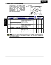
ON When the Boolean operation specified by C143
has a logical “1” result
09 LOG Logic Output Function
OFF When the Boolean operation specified by C143
has a logical “0” result
ON No communication between communication
option is detected during a time set in P044
10 ODc Communication option
error
OFF Communication is normal
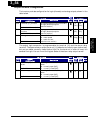
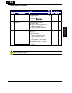
ON Motor current is less than the set value of C03943 LOC Low load detection
OFF Motor current is not less than the set value of
C039
3
−
55
Configuring Drive
Parameters