


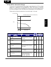
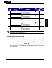
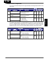
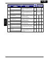
Output Terminal Configuration
The inverter provides configuration for logic (discrete) and analog outputs, shown in the
table below.
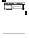
“C” Function Defaults
Func.
Code
Name /
SRW Display
Description
Run
Mode
Edit
-FE
(EU)
-FU
(USA)
Units
Terminal [11] functionC021
OUT-TM 11 FA1
12 programmable functions available
for logic (discrete) outputs
(see next section)
U
01
[FA1]
01
[FA1]
−
Alarm relay terminal
function
C026
OUT-TM RY AL
12 programmable functions available
for logic (discrete) outputs
(see next section)
U
05
[AL]
05
[AL]
−
AM signal selectionC028
AM-KIND F
Two available functions:
00…motor speed
01…motor current
(see after next section)
U
00
[freq]
00
[freq]
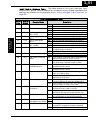
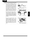
The output logic conversion is programmable for terminal [11] and the alarm relay
terminal. The open-collector output terminal [11] defaults to normally open (active low),
but you can select normally closed (active high) for the terminal in order to invert the
sense of the logic. You can invert the logical sense of the alarm relay output as well.
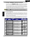
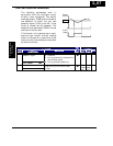
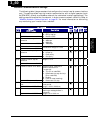
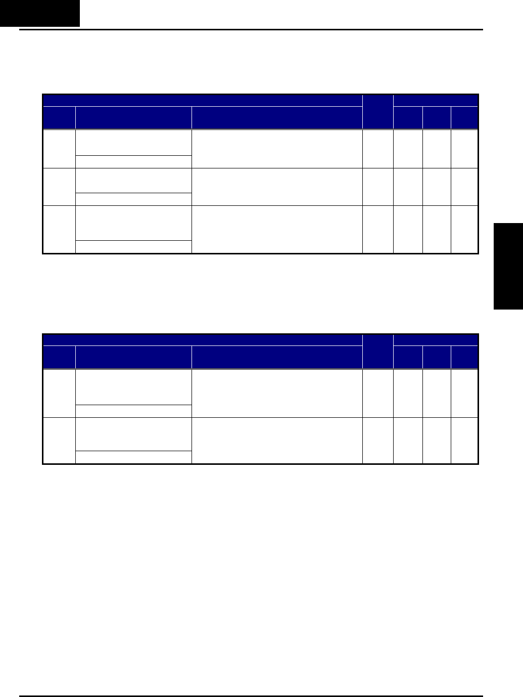
“C” Function Defaults
Func.
Code
Name /
SRW Display
Description
Run
Mode
Edit
-FE
(EU)
-FU
(USA)
Units
Terminal [11] active
state
C031
O/C-11 NO
Select logic conversion, two option
codes:
00…normally open [NO]
01…normally closed [NC]
U
00 00
−
Alarm relay active stateC036
O/C-RY NC
Select logic conversion, two option
codes:
00…normally open [NO]
01…normally closed [NC]
U
01 01
−
3−54
Configuring Drive
Parameters