


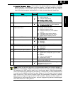

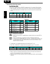
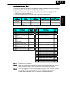
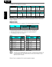
6. Inverter Parameter Setup - The inverter has several settings related to ModBus
communications. The table below lists them together. The
Required
column indicates
which parameters
must
be set properly to allow communications. You may need to
refer to the host computer documentation in order to match some of its settings.
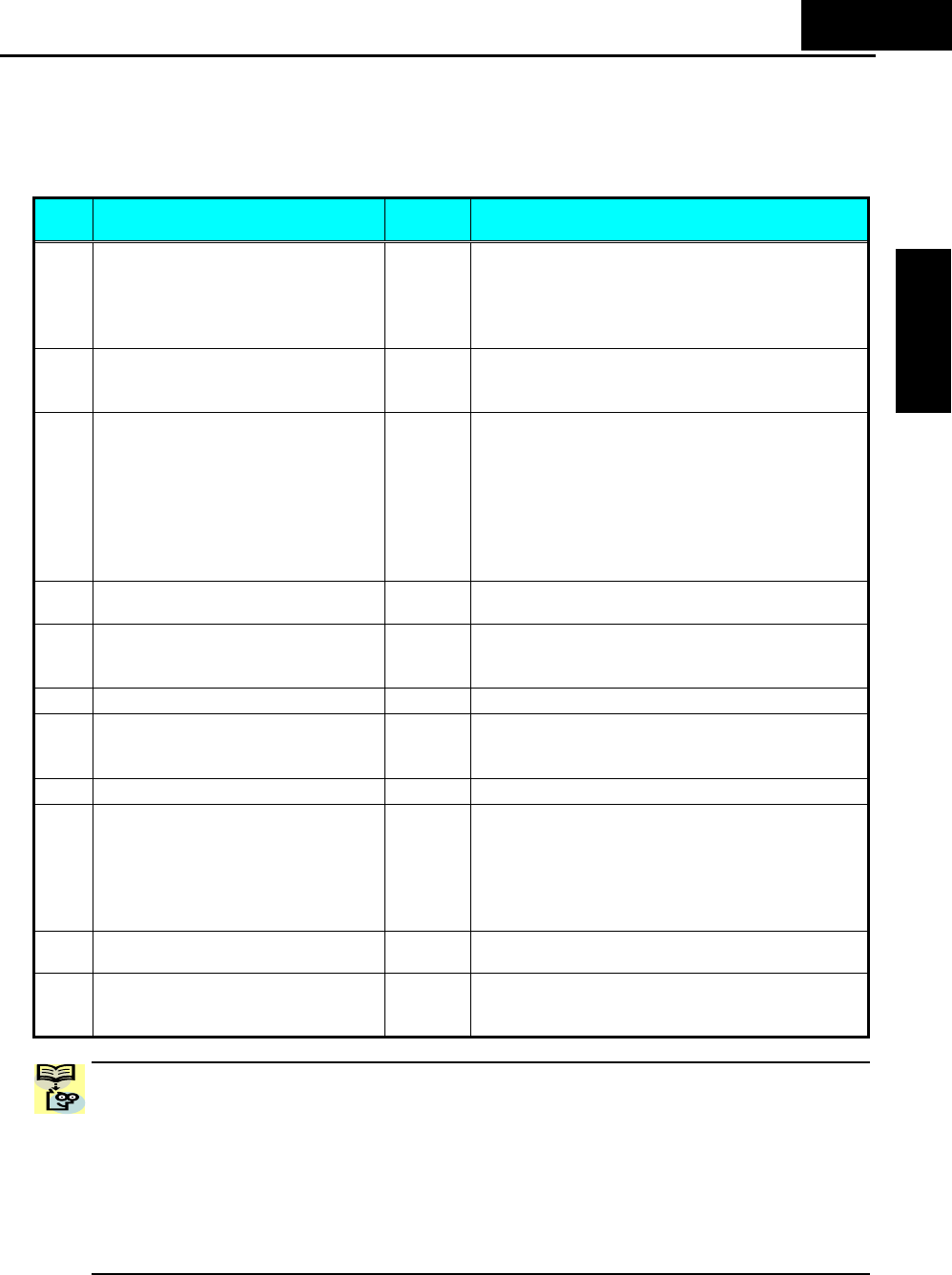
Func.
Code
Name Required Settings
A001 Frequency source setting
9
00…Keypad potentiometer
01…Control terminal
02…Function F001 setting
03…ModBus network input
10…Calculate function output
A002 Run command source setting
9
01…Control terminal
02…Run key on keypad, or digital operator
03… ModBus network input
B089 Monitor display select for
networked inverter
−
01…Output frequency monitor
02…Output current monitor
03…Rotation direction monitor
04…Process variable (PV), PID feedback
monitor
05…Intelligent input terminal status
06…Intelligent output terminal status
07…Scaled output frequency monitor
C070 Selection of OPE/ModBus
9
02...OPE or option
03...ModBus (485)
C071 Communication speed selection
9
04…4800 bps
05…9600 bps
06…19200 bps
C072 Node allocation
9
Network address, range is 1 to 32
C074 Communication parity selection
9
00…No parity
01…Even parity
02…Odd parity
C075 Communication stop bit selection
9
Range is 1 to 2
C076 Communication error select
−
00…Trip (Error code E60)
01…Decelerate to a stop and trip (Error code
E60)
02…Disable
03…Free run stop (coasting)
04…Decelerate to a stop
C077 Communication error time-out
−
Comm. Watchdog timer period,
range is 0.00 to 99.99 sec.
C078 Communication wait time
9
Time the inverter waits after receiving a
message before it transmits.
Range is 0. to 1000. ms
NOTE: When you edit and store any of the parameters above, the inverter causes it to
take effect immediately. ModBus transmission occurs only after you set the OPE/485
DIP switch to the “485” position and turn on the inverter again. Note that parameters
C070 to C078 cannot be changed via the network. To edit them, you must disconnect the
inverter from the ModBus and wait for about 30sec until the inverter’s internal keypad
begin functioning. Then use this keypad to edit the parameters. Please don’t connect
other external programming devices to RJ45 connector, because the bus mode is in
RS485 mode. It may cause the inverter or external programming devices to be damaged
when DIP switch is in “485” position.
B
−
5
Appendix B