


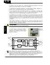
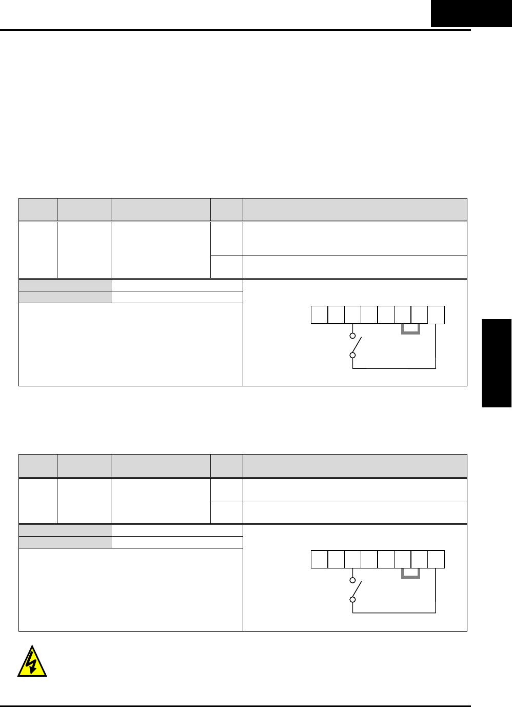
Force Terminal Mode
The purpose of this intelligent input is to allow a device to force the inverter to allow
control of the following two parameters via the control terminals:
• A001 - Frequency source setting (01 = control terminals [FW] and [RV]
• A002 - Run command source setting (01 = control terminals [O] or [OI]
Some applications will require one or both settings above to use a source other than the
terminals. You may prefer to normally use the inverter’s keypad and potentiometer, or
to use the ModBus network for control, for example. However, an external device can
turn ON the [F-TM] input to force the inverter to (temporarily) allow control (frequency
source and Run command) via control terminals. When the [F-TM] input is OFF, then
the inverter uses the regular sources specified by A001 and A002 again.
Option
Code
Terminal
Symbol
Function Name State Description
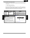
ON Forces A001=01 (frequency source setting =
control terminal), and A002=01(Run command
source setting = control terminal)
51 F-TM Force Terminal
Mode
OFF Inverter applies the user setting for A001 and
A002 normally
Valid for inputs: C001~C005
Required settings A001, A002
Notes:
• When changing the [F-TM] state during Run
Mode (inverter is driving the motor), the
inverter will stop the motor before the new [F-
TM] state takes effect.
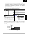
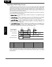
Example (default input configuration shown—see
page 3–49):
See I/O specs on page 4–6.
Inverter Ready
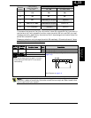
The purpose of this intelligent input is to make inverter ready to start the motor
immediately when the RUN command is given. When the RDY input is active, motor
output terminal is active even if there is no RUN command.
Option
Code
Terminal
Symbol
Function Name State Description
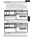
ON Inverter is ready to act immediately when the
RUN command is given.
52 RDY Inverter Ready
OFF Inverter performs normal start when the RUN
command is given.
Valid for inputs: C001~C005
Required settings A001, A002
Notes:
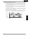
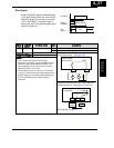
Example (default input configuration shown—see
page 3–49):
See I/O specs on page 4–6.
H
IGH VOLTAGE: When set RDY function ON, there will be a voltage appear at
m
otor output terminals U, V and W even if the motor is in stop mode. So never touch
t
he inverter power terminal even the motor is not running.
5 4 3 2 1 L
PCS
P24
F-TM
4
−
31
Operations and
Monitoring
5 4 3 2 1 L
PCS
P24
RDY