


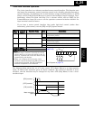
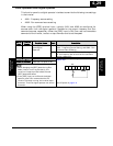
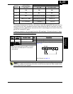
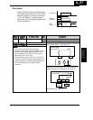
Safety Stop switch condition
Terminal
Number
Default setting
Safety Stop switch
S8 = OFF
Safety Stop switch
S8 = ON
Safety Stop switch
S8 = ON Æ OFF
1FW FW FW
2RV RV RV
3CF1
EMR
[HW based for 1b input]
- (No func.)
4CF2 [US ver. :USP]
RS
[HW based for 1a input]
RS
[Normal 1a]
5
RS
(PTC assignable)
- (No func.) - (No func.)
This means that terminal 5 will be “no function” when S8 is made ON. So if you want to
use the terminal 5 with a specific function under the switch S8 is turned ON, you need
to assign manually. Additionally the terminal 3 will also change to no function when the
switch S8 is made OFF again.
Please pay attention not to change the switch S8 needlessly. Otherwise there will be an
unexpected performance of your system.
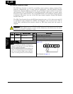
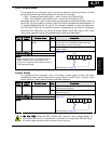
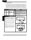
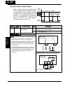
Option
Code
Terminal
Symbol
Function Name State Description
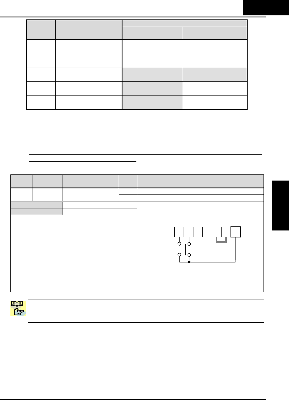
ON Emergency signal is activated64 EMR Safety Stop
OFF Emergency signal is not activated
Valid for inputs: C001~C005
Required settings
Notes:
• Both active state (normally open or normally
close) setting of EMR and EXT must be the
same setting.
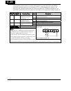
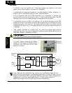
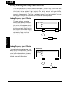
Example (default input configuration shown—see
page 3–49):
See I/O specs on page 4–6.
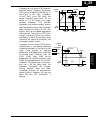
NOTE: In any case the total system (including the inverter unit) must comply to
EN60204-1 (safety of machinery) and other norms that are required. Refer to each norm
that is required on your system.
5 4 3 2 1 L
PCS
P24
EMRRS
4
−
33
Operations and
Monitoring