


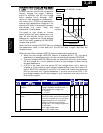
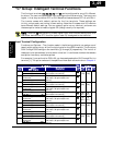
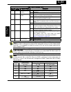
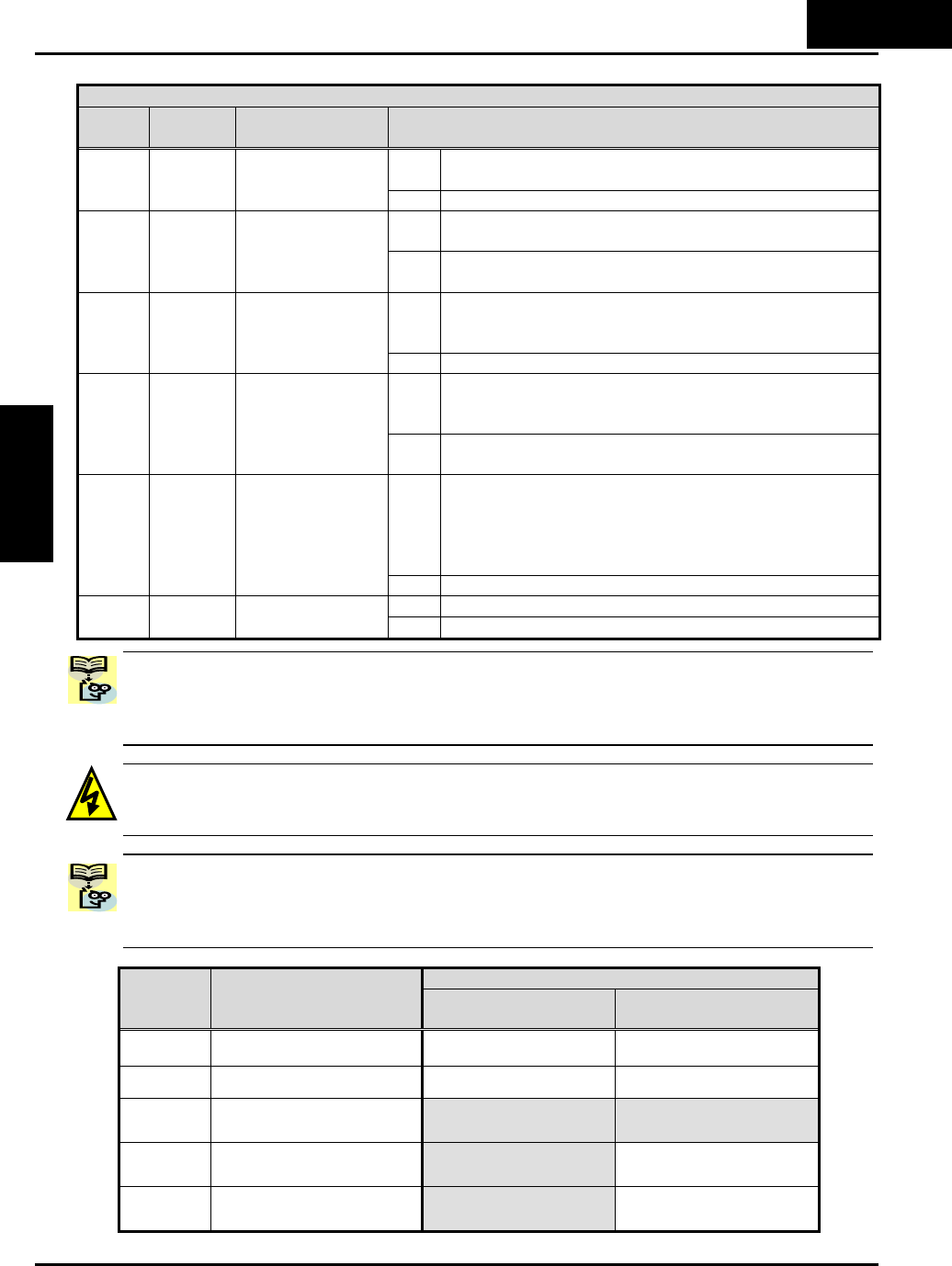
Input Function Summary Table
Option
Code
Terminal
Symbol
Function Name Description
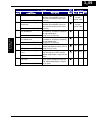
ON Adds the A145 (add frequency) value to the output
frequency
50 ADD ADD frequency
enable
OFF Does not add the A145 value to the output frequency
ON Force inverter to use input terminals for output
frequency and Run command sources
51 F-TM Force Terminal
Mode
OFF Source of output frequency set by A001 and source of
Run command set by A002 is used
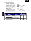
ON To charge up the internal boot-strap capacitor so to
start motor immediately after the RUN command is
given.
52 RDY * Inverter Ready
OFF Inverter operates normal.
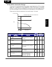
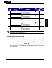
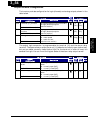
ON The inverter uses 2nd motor parameters for generating
frequency output to motor. The selection of 1st or 2nd
motor is available during Stop Mode or Run Mode.
53 SP-SET Special set
OFF The inverter uses 1st (main) motor parameters for
generating frequency output to motor.
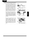
ON Inverter recognizes that the emergency signal is given,
and shuts off the output.
Use together with EXT input when the system
including the inverter must comply to EN954-1.
Refer to “Safe Stop” on page 4-32.
64 EMR * Safe Stop
OFF Inverter operates normal
ON (input ignored)255 - (No function)
OFF (input ignored)
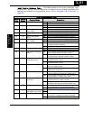
NOTE: When using the Multi-speed Select settings CF1 to CF4, do not display
parameter F001 or change the value of F001 while the inverter is in Run Mode (motor
running). If it is necessary to check the value of F001 during Run Mode, lease monitor
D001 instead of F001.
HIGH VOLTAGE: When set RDY function ON, there will be a voltage appears at motor
output terminals U, V and W even if the motor is in stop mode. So never touch the
inverter power terminals even the motor is not running.
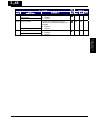
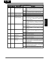
NOTE: The EMR is not programmable, but will be assigned automatically when the
hardware switch S8 is made ON. When the EMR is assigned, function assignments of
terminal 3, 4 and 5 are automatically changed as follows. Please also refer to Safety
Stop paragraph.
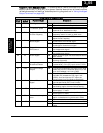
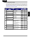
Safety Stop switch condition
Terminal
Number
Default setting
Safe Stop switch
S8 = OFF
Safety Stop switch
S8 = ON
Safety Stop switch
S8 = ON Æ OFF
1FW FW FW
2RV RV RV
3CF1
EMR
[HW based for 1b input]
- (No func.)
4CF2 [US ver. :USP]
RS
[HW based for 1a input]
RS
[Normal 1a]
5
RS
(PTC assignable)
- (No func.) - (No func.)
3
−
53
Configuring Drive
Parameters