


Choosing a Programming Device
Introduction
Hitachi variable frequency drives (inverters) use the latest electronics technology for
getting the right AC waveform to the motor at the right time. The benefits are many,
including energy savings and higher machine output or productivity. The flexibility
required to handle a broad range of applications has required ever more configurable
options and parameters – inverter are now a complex industrial automation component.
And this can make a product seem difficult to use, but the goal of this chapter is to make
this easier for you.
As the powerup test in Chapter 2 demonstrated, you do not have to program very many
parameters to run the motor. In fact, most applications would benefit only from
programming just a few, specific parameters. This chapter will explain the purpose of
each set of parameters, and help you choose the ones that are important to your
application.
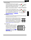
If you are developing a new application for the inverter and a motor, finding the right
parameters to change is mostly an exercise in optimization. Therefore, it is okay to
begin running the motor with a loosely tuned system. By making specific, individual
changes and observing their effects, you can achieve a finely tuned system.
Introduction of Inverter Programming
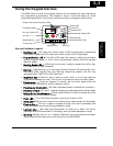
The front panel keypad is the first and best way to get to know the inverter’s
capabilities. Every function or programmable parameter is accessible from the keypad.
The other devices simply imitate the keypad’s layout and inverter access, while adding
another valuable aspect to the system. For example, the Digital Operator/Copy Unit can
transfer one inverter’s parameter settings to another inverter, while still providing
standard operator keypad control. In this way, you can use a variety of programming
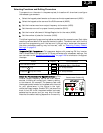
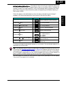
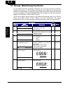
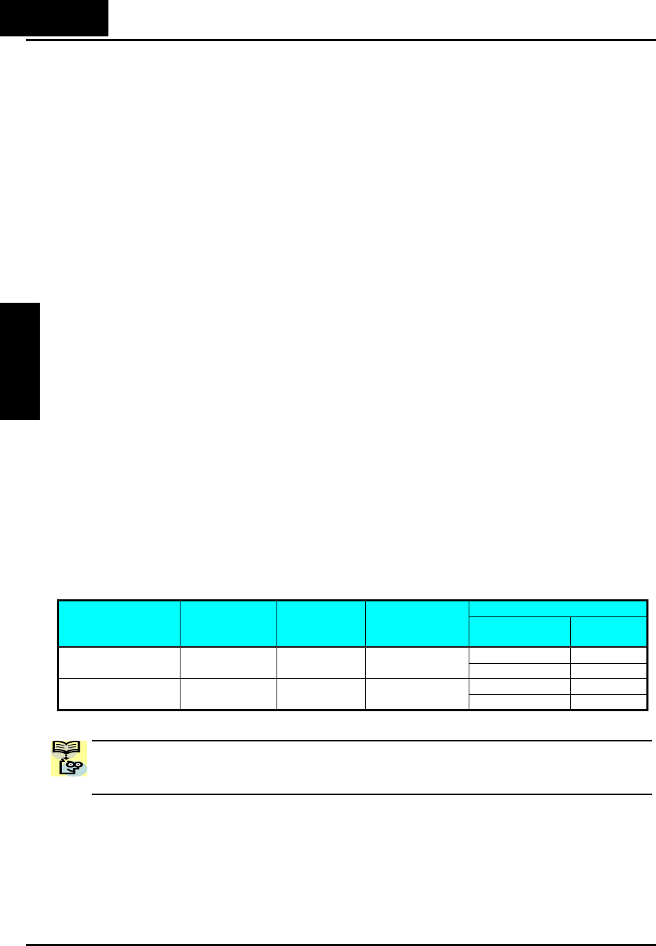
devices with basically the same keypad skills. The following table shows various
programming options, the features unique to each device, and the cables required.
Cables (choose one)
Device
Part
Number
Parameter
Access
Parameter
setting
storage
Part number Length
ICS-1 1 meter
External inverter
keypad
OPE-SRmini
Monitor and
Program
EEPROM in
inverter
ICS-3 3 meters
ICS-1 1 meter
Digital Operator/
Copy Unit
SRW-0EX
Monitor and
Program
EEPROM in
operator panel
ICS-3 3 meters
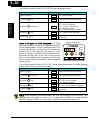
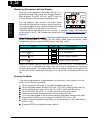
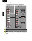
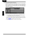
NOTE: When an external digital operator device such as an OPE-SRmini or SRW-0EX
is connected to the inverter, the inverter’s keypad is automatically disabled (except for
the Stop Key).
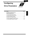
3−2
Configuring Drive
Parameters