


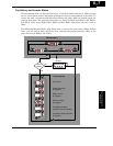
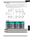

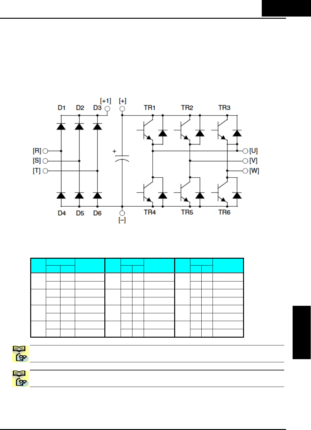
IGBT Test Method
The following procedure will check the inverter transistors (IGBTs) and diodes:
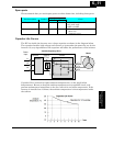
1. Disconnect input power to terminals [R, S, and T] and motor terminals [U, V, and W].
2. Disconnect any wires from terminals [+] and [–] for regenerative braking.
3. Use a Digital Volt Meter (DVM) and set it for 1Ω resistance range. You can check the
status of the charging state of terminals [R, S, T, U, V, W, +, and –] of the inverter
and the probe of the DVM by measuring the charging state.
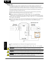
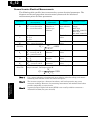
Table Legend Almost infinite resistance: ≅ ∞ Ω Almost zero resistance: ≅ 0 Ω
DVM DVM DVMPart
+ –
Measured
Value
Part
+ –
Measured
Value
Part
+ –
Measured
Value
[R] [+1]
≅ ∞ Ω
[S] [–]
≅ 0 Ω
[W] [+]
≅ ∞ Ω
D1
[+1] [R]
≅ 0 Ω
D5
[–][S]
≅ ∞ Ω
TR3
[+] [W]
≅ 0 Ω
[S] [+1]
≅ ∞ Ω
[T] [–]
≅ 0 Ω
[U] [–]
≅ 0 Ω
D2
[+1] [S]
≅ 0 Ω
D6
[–][T]
≅ ∞ Ω
TR4
[–][U]
≅ ∞ Ω
[T] [+1]
≅ ∞ Ω
[U] [+]
≅ ∞ Ω
[V] [–]
≅ 0 Ω
D3
[+1] [T]
≅ 0 Ω
TR1
[+] [U]
≅ 0 Ω
TR5
[–][V]
≅ ∞ Ω
[R] [–]
≅ 0 Ω
[V] [+]
≅ ∞ Ω
[W] [–]
≅ 0 Ω
D4
[–][R]
≅ ∞ Ω
TR2
[+] [V]
≅ 0 Ω
TR6
[–][W]
≅ ∞ Ω
NOTE: The resistance values for the diodes or the transistors will not be exactly the
same, but they will be close. If you find a significance difference, a problem may exist.
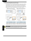
NOTE: Before measuring the voltage between [+] and [–] with the DC current range,
confirm that the smoothing capacitor is discharged fully, then execute the tests.
6
−
15
Troubleshooting and
Maintenance