


Vol. 2A 3-3
INSTRUCTION SET REFERENCE, A-M
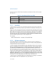
3.1.1.2 Instruction Column in the Opcode Summary Table
The “Instruction” column gives the syntax of the instruction statement as it would
appear in an ASM386 program. The following is a list of the symbols used to repre-
sent operands in the instruction statements:
• rel8 — A relative address in the range from 128 bytes before the end of the
instruction to 127 bytes after the end of the instruction.
• rel16, rel32, rel64 — A relative address within the same code segment as the
instruction assembled. The rel16 symbol applies to instructions with an operand-
size attribute of 16 bits; the rel32 symbol applies to instructions with an
operand-size attribute of 32 bits; the rel64 symbol applies to instructions with an
operand-size attribute of 64 bits.
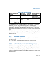
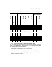
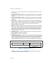
BL None 3 BX None 3 EBX None 3 RBX None 3
AH Not
encod
able
(N.E.)
4 SP None 4 ESP None 4 N/A N/A N/A
CH N.E. 5 BP None 5 EBP None 5 N/A N/A N/A
DH N.E. 6 SI None 6 ESI None 6 N/A N/A N/A
BH N.E. 7 DI None 7 EDI None 7 N/A N/A N/A
SPL Yes 4 SP None 4 ESP None 4 RSP None 4
BPL Yes 5 BP None 5 EBP None 5 RBP None 5
SIL Yes 6 SI None 6 ESI None 6 RSI None 6
DIL Yes 7 DI None 7 EDI None 7 RDI None 7
Registers R8 - R15 (see below): Available in 64-Bit Mode Only
R8L Yes 0 R8W Yes 0 R8D Yes 0 R8 Yes 0
R9L Yes 1 R9W Yes 1 R9D Yes 1 R9 Yes 1
R10L Yes 2 R10W Yes 2 R10D Yes 2 R10 Yes 2
R11L Yes 3 R11W Yes 3 R11D Yes 3 R11 Yes 3
R12L Yes 4 R12W Yes 4 R12D Yes 4 R12 Yes 4
R13L Yes 5 R13W Yes 5 R13D Yes 5 R13 Yes 5
R14L Yes 6 R14W Yes 6 R14D Yes 6 R14 Yes 6
R15L Yes 7 R15W Yes 7 R15D Yes 7 R15 Yes 7
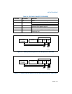
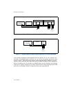
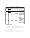
Table 3-1. Register Codes Associated With +rb, +rw, +rd, +ro (Contd.)
byte register word register dword register quadword register
(64-Bit Mode only)
Register
REX.B
Reg Field
Register
REX.B
Reg Field
Register
REX.B
Reg Field
Register
REX.B
Reg Field