


Section 8: Adjustment Procedures
M84Pro Service Manual PN 9001111A Page 8-10
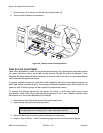
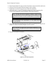
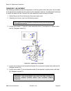
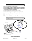
4 Turn the knurled knob of sensor adjustment shaft (2) to laterally adjust sensors (3) and (4).
5 Close/install housing covers.
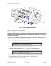
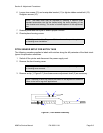
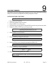
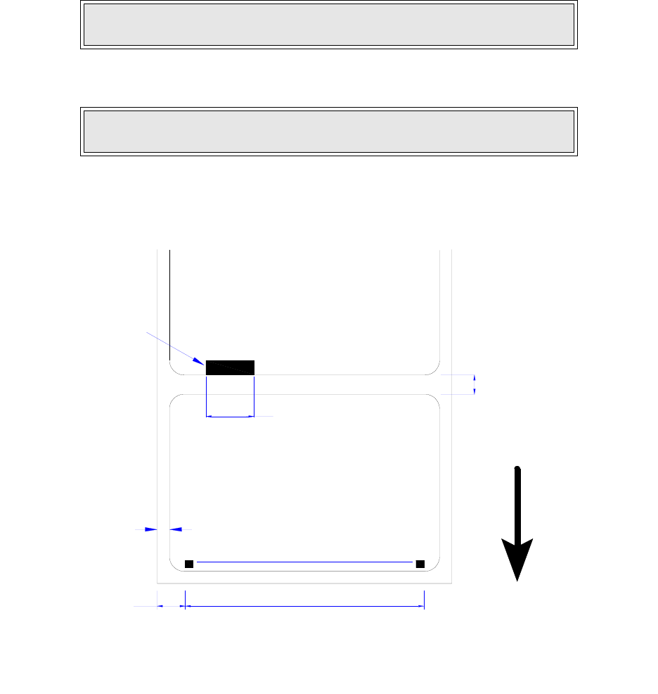
Figure 8-8, Label Stock Diagram
PRINT POSITION ADJUSTMENT
There are three methods of print position adjustment. Two of the methods allow for coarse
adjustment, and the third permits fine adjustment.
Although there are three methods, only two are recommended for non-SATO personnel. For this
reason, the VR1 potentiometer located on the main circuit board will only be identified here and
not explained.
NOTE: Adjust sensor to align with, and register; the label hole, notch, gap, or
edge as applicable.
NOTE: Figure 10-1 in the Diagrams & Schematics section provides guidance
on housing cover installation.
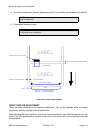
LABEL
BACKING PAPER INSIDE EDGE
LABEL INSIDE EDGE
14MM MINIMUM
DOT COLUMN NUMBER
104MM
3MM
832
1
DIE CUT INTER-LABEL GAP 3MM NOMINAL
EYE-MARK ON BOTTOM OF LINER
LABEL
LABEL FEED DIRECTION
LABEL GAP - 17 TO 64MM ADJUSTMENT
EYE-MARK - 7 TO 54MM ADJUSTMENT