


Section 8: Adjustment Procedures
M84Pro Service Manual PN: 9001111A Page 8-13
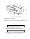
EYE-MARK SENSOR ADJUSTMENT
This adjustment will require the use of a multimeter and the TP Test Module.
1 Open/remove the top, right, and left housing covers.
2 Turn the VR5 potentiometer fully counter-clockwise.
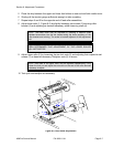
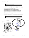
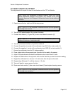
3 Connect test module (1, Figure 8-9) to main circuit board connector (2).
4 Turn dial (3) on test module (1) to position number 4.
5 Connect the positive (+) probe of the multimeter to pin SIG (4) on test module (1).
6 Connect the negative (-) probe of the multimeter to pin GND (5) on test module (1).
7 Ensure the multimeter is set for DC voltage reading.
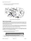
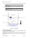
8 Place a label without the eye-mark part in position to be read by the sensor.
9 Adjust VR4 potentiometer so that the multimeter value is less than 0.5 volts.
10 Replace the label without the eye-mark with one that has the eye-mark for sensor reading.
11 Regard the millimeter for a value of +1.0 volts more than the prior value read.
12 Repeat steps 8 through 11 until the value is +1.0 volts.
13 Test print labels to ensure proper function.
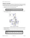
14 Disconnect test module (1) from main circuit board (2) and replace housing covers.
NOTE: Figure 10-5, Accessories & Sensors Location; Figure 10-6, Print
Position Reference Diagram; and Figures 10-7 through 10-19, Print
Operation Sequence in the Diagram & Schematics Section provide additional
instruction.
NOTE: Figure 10-1 in the Diagrams & Schematics section provides guidance
on housing cover removal.
NOTE: Refer to TP Test Module Usage in the Troubleshooting section for
additional instruction on test module use.
NOTE: Figure 10-1 in the Diagrams & Schematics section provides guidance
on housing cover installation.