


Section 6: Troubleshooting
M84Pro Service Manual PN 9001111A Page 6-8
7 Troubleshoot and/or replace components as directed in their respective procedures.
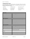
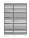
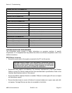
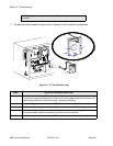
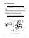
Figure 6-1, TP Test Module Usage
NOTE: Voltage readings must be +/- 10% of specification for proper
operation.
DIAL APPLICATION DESCRIPTION
0 through 3 Used to determine voltage. Refer to the specifications section of this manual to determine
a component’s required voltage level. Set the dial to that voltage requirement and the milli-
meter reading should be in the same range if properly performing.
4 Used for testing and adjustment of the VR5 potentiometer when Eye-Mark printing.
5 Used for testing and adjustment of the VR4 potentiometer when GAP printing.
6 Used for testing and adjustment of the VR2 potentiometer when printing with dispencer.
The potentiometer should be turned fully clock-wise for this operation.
7 Used for testing and adjustment of the VR3 potentiometer for ribbon end sensing.
I
E
E
E
1
2
8
4
+
R
S
B
O
A
R
D
0
1
2
8
7
6
5
4
3
G
N
D
S
I
G
1
A
2
A
3
A
4
A
6
B
5
B
4
B
3
B
1
B
2
B
6
A
5
A
2
6
5
A
6
A
2
B
1
B
3
B
4
B
5
B
6
B
4
A
3
A
2
A
1
A
S
I
G
G
N
D
3
4
5
6
7
8
2
1
0
1
1
5
3
4