


Section 7: Replacement Procedures
M84Pro Service Manual PN: 9001111A Page 7-21
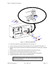
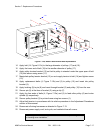
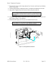
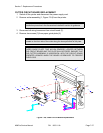
7 Disconnect the sensor switch wiring harness from the main circuit board and withdraw
switch (1) from printer.
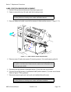
8 Feed the wiring harness of replacement switch (1) through the slot adjacent to the motor.
9 Apply switch (1) against the printer frame and secure using two screws (8).
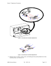
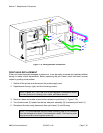
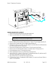
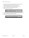
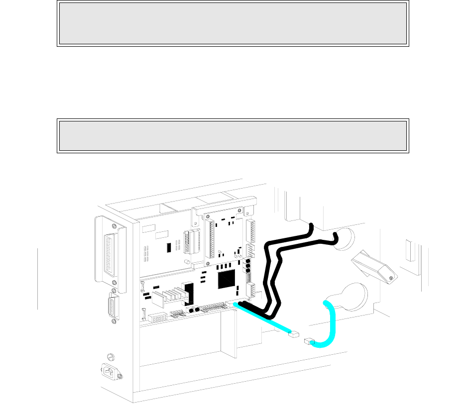
10 Connect the wiring harness of replacement label-out sensor switch (1) to the main circuit
board. Refer to Figure 7-16 for guidance.
11 Reconnect power supply cord, test cycle, and reattach/close all covers.
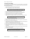
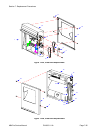
Figure 7-16, Wiring Harness Connection
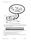
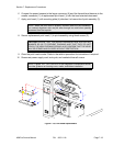
NOTE: A properly oriented sensor switch will permit its mounting orifices to
align with those of the frame while its contact arm protrudes through the
paper ramp.
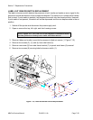
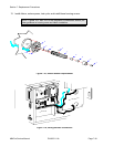
NOTE: Figures 10-1, 10-2, and 10-3 of the Daigrams & Schematics section
provides guidance on housing cover, media, and ribbon installation.
I
E
E
E
1
2
8
4
+
R
S
B
O
A
R
D
P
O
W
E
R
B
O
A
R
D
B
E
L
T
C
O
N
F
I
G
U
R
A
T
I
O
N