


Section 3: Interface Specifications
M84Pro Service Manual PN: 9001113A Page 3-5
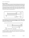
READY/BUSY FLOW CONTROL
Ready/Busy is the hardware flow control method for the serial interface on the M-84PRO
printers. By raising/lowering the voltage level on Pin 20 of the RS232C port, the printer notifies
the host when it is ready to receive data. Pin 4 (RTS) and pin 20 (DTR) are the important signals
on the printer for this method of flow control. The host must be capable of supporting this flow
control method for it to function properly.
X-O
N/X-OFF FLOW CONTROL
X-On/X-Off flow control is used whenever hardware (Ready/Busy) flow control is not available or
desirable. Instead of a voltage going high/low at pin 20, control characters representing ìPrinter
Readyî (X-On =11 hexadecimal) or “Printer Busy” (X-Off = 13 hexadecimal) are transmitted by
the printer on pin 2 (Transmit Data) to the host. In order for this method of flow control to function
correctly, the host must be capable of supporting it. X-On/X-Off operates in a manner similar to
the function of pin 20 (DTR) as previously explained. When the printer is first powered on it sends
an X-Off when the “Buffer Near Full” level is reached and a X-On when the data level of the buffer
drops below the “Buffer Available” mark. When the printer is taken off-line manually, it transmits
an X-Off indicating it cannot accept data. When it is placed back on line manually, it sends an X-
On, indicating it is again available for receipt of data. If an error occurs during printing (paper out,
ribbon out), the printer sends an X-Off as soon as an error condition is detected. When the error
is cleared and the printer is placed back on-line, it transmits an X-On indicating it is again ready
to accept data. Upon power up if no error conditions are present, the printer will continually send
X-On characters at five millisecond intervals until it receives a transmission from the host.
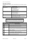
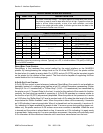
20 To Host DTR (Data Terminally Ready) - This signal applies to Ready/Busy flow control.
The printer is ready to receive data when this pin is high. It goes low when the
printer is off-line, either manually or due to an error condition, and while
printing in the single job buffer mode. It will also go low when the data in the
buffer reaches the buffer near full level.
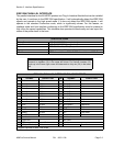
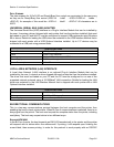
CABLE REQUIREMENTS
DB9 DB25 HOST INTERCONNECTION DB25 PRINTER
1 1 FG <---------------- 1 FG (Frame Ground)
2 3 RD ----------------> 2 TD (Transmit Data)
3 2 TD <---------------> 3 RD (Receive Data)
8 5 CTS I--------
I--------
4 RTS (Request to Send)
7 4 RTS 5 CTS (Clear to Send)
4 20 DTR I--------
<-----------------
6 DSR (Data Set Ready)
6 6 DSR* 20 DTR (Data Terminal Ready)
5 7 SG <---------------> 7 SG (Signal Ground)
* This connection at the host side of the interface would depend upon the pin that is being used as the
Ready/Busy signal by the driving software. Typically, on a PC, it would be either CTS (pin5) or DSR (pin
6) on a DB-25 connector.
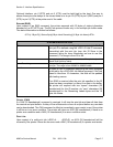
RS232C SERIAL INTERFACE SIGNALS
PIN DIRECTION SIGNAL DEFINITION