


M84Pro Service Manual PN: 9001111A Page 5-1
5
PRINTER CONFIGURATION
This section provides configuration instructions. Figures 10-7 through 10-19 in the Diagrams &
Schematics section provides diagrams and charts on print operation sequence.
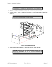
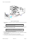
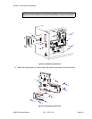
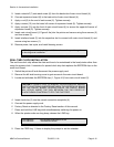
DIP SWITCH PANELS
There are two DIP switches (DSW2 and DSW3) located on the front panel under a protective
cover. A third DIP switch is located on the RS232C Serial Adapter card and is used to set the
RS232C transmit/receive parameters. Each switch is an eight section on/off toggle type switch.
The ON position is always oriented upward and consequently, the off is always downward.
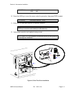
Switch settings are read by the printer electronics during the power up sequence and will not
become effective until the power is cycled.
RS232 TRANSMIT/RECEIVE SETTING
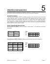
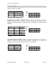
Data Bit Selection (DSW1-1): Sets the printer to receive either 7 or 8 data bits for each byte
transmitted.
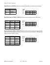
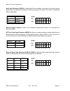
Parity Selection (DSW1-2, DSW1-3): Selects the type of parity used for error detection.
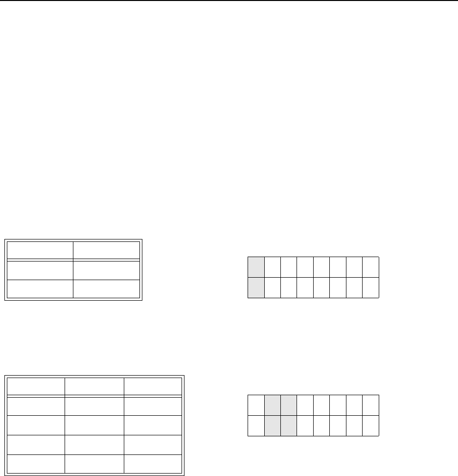
DSW1-1 SETTING
Off 8 Data Bits
On 7 Data Bits
DSW1
ON
OFF
12345678
DSW1-1 DSW1-3 SETTING
Off Off No Parity
Off On Even
On Off Odd
On On Not Used
DSW1
ON
OFF
12345678