


Section 7: Replacement Procedures
M84Pro Service Manual PN 9001111A Page 7-2
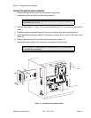
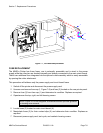
4 Remove two screws (3) securing interface board (4) to printer housing.
5 Withdraw interface board (4) from its connection with main circuit board (1).
6 Remove three screws (5) securing daughter board (2) to main circuit board (1).
7 Withdraw daughter board (2) from its connection with main circuit board (1).
8 Detach optional memory card (6) from its connection with main circuit board (1).
9 Remove two exterior screws (7) securing main circuit board (1) to the housing.
10 Remove three interior screws (8) securing main circuit board (1) to the printer frame.
11 Withdraw main circuit board (1) from within the printer.
12 Prepare to replace main circuit board (1).
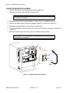
13 Install main circuit board (1) into mounting position and secure to the printer frame using
three screws (8).
14 Secure the exterior of main circuit board (1) using two screws (7).
15 Connect optional memory card (6) to main circuit board (1) as applicable.
16 Connect and attach daughter board (2) to main circuit board (1) using three screws (5).
17 Connect interface board (4) to main circuit board (1) and secure to housing using two
screws (3).
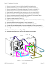
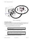
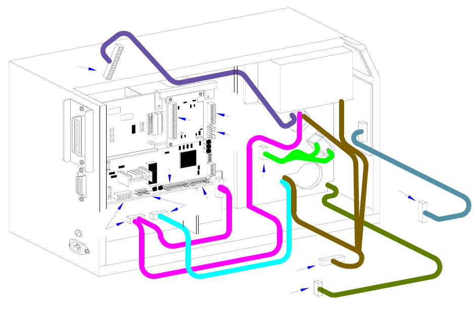
18 Reconnect all wiring harnesses (Figure 7-2).
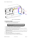
19 Reconnect power supply cord, test cycle, and reattach housing covers.
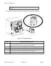
Figure 7-2, Circuit Board Replacement
I
E
E
E
1
2
8
4
+
R
S
B
O
A
R
D
C
A
B
D
G
F
E
F
E
D
C
G