


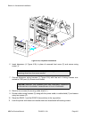
Section 4: Accessories Installation
M84Pro Service Manual PN: 9001111A Page 4-9
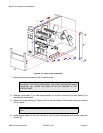
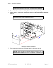
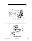
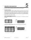
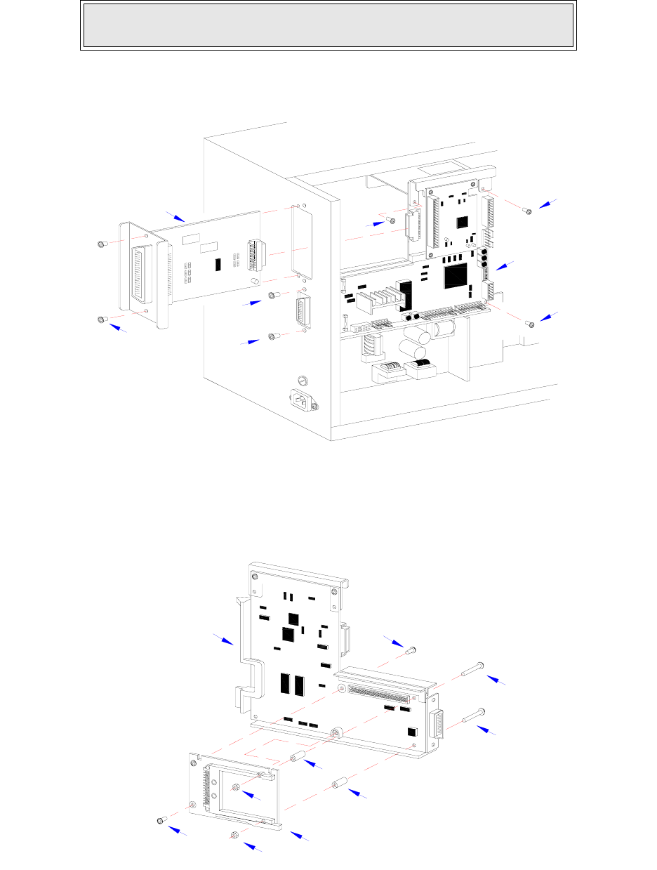
Figure 4-4a, Memory Expansion
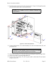
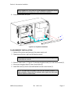
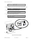
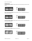
8 Insert two long screws (6, Figure 4-4b) into main circuit board (4) from the front.
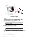
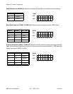
Figure 4-4b, Memory Expansion
NOTE: It is advised that all wiring harnesses remain connected during
expansion board instalation to prevent the possibility of incorrect connections.
I
E
E
E
1
2
8
4
+
R
S
B
O
A
R
D
2
1
5
5
5
3
3
4
7
6
9
10
8
6
4
10
9
7