


Section 7: Replacement Procedures
M84Pro Service Manual PN: 9001111A Page 7-23
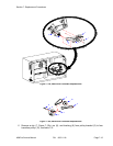
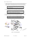
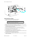
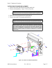
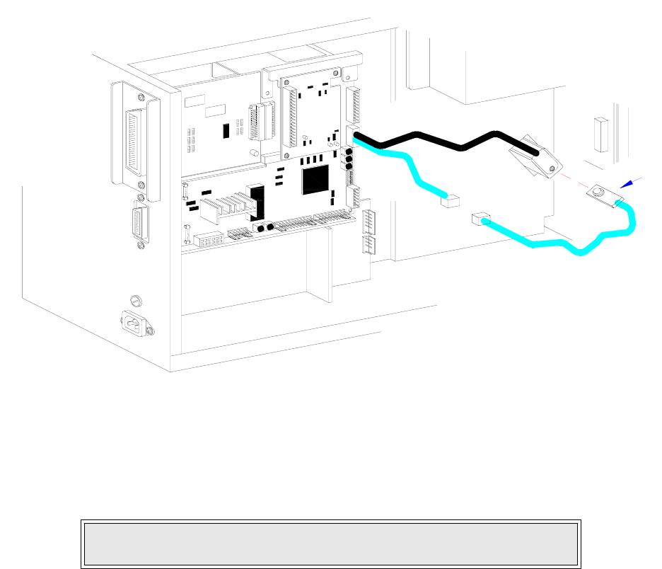
Figure 7-18, Wiring Harness Connection
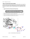
RIBBON SENSOR REPLACEMENT
1 Switch off the printer and disconnect the power supply cord.
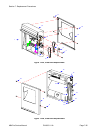
2 Open or remove the top, left, and right housing covers.
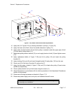
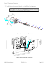
3 Remove ribbon to allow access to ribbon sensor (1, Figure 7-21) and supply assembly (2).
4 Remove screw (3) and screw (4) from ribbon supply assembly (2).
5 Withdraw boss cap (5), two collars (6), ribbon boss (7), another collar (6), and disk plate (8)
from ribbon supply shaft (9) consecutively.
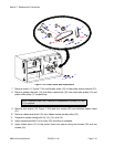
6 Disconnect the wiring harness of ribbon sensor (1) from the main circuit board.
7 Remove screw (10) securing ribbon sensor (1) to printer frame. Lift away sensor (1).
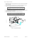
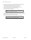
8 Route replacement sensor (1) through printer frame.
9 Secure replacement sensor (1) to printer frame using screw (10).
10 Apply disk plate (8), a collar (6), ribbon boss (7), two additional collars (6), and boss cap (5)
onto ribbon supply shaft (9) and secure with screw (4).
11 Align orifices of boss (7) and shaft (9) and apply screw (3).
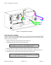
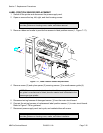
12 Connect wiring harness of replacement ribbon sensor (1) to main circuit board. Refer to
Figure 7-22 for guidance.
NOTE: Figures 10-1 and 10-3 of the Daigrams & Schematics section pro-
vides guidance on housing cover and ribbon removal.
I
E
E
E
1
2
8
4
+
R
S
B
O
A
R
D
B
E
LT
C
O
N
F
I
G
U
RA
T
I
ON
1