


M84Pro Service Manual PN: 9001111A Page 7-1
7
REPLACEMENT PROCEDURES
The M84PRO Printer contains replaceable components and sub-assemblies. This section
contains step-by-step instructions for the removal and replacement of those primary components
and sub-assemblies that are subject to wear or damage.
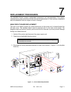
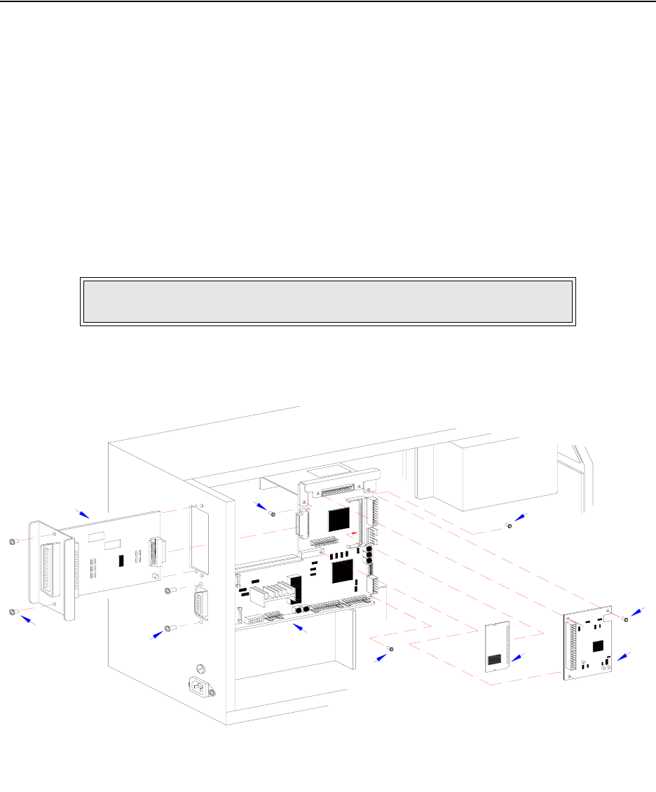
MAIN CIRCUIT BOARD REPLACEMENT
The main circuit board contains the control electronics for the printer and is located behind the
left side cover. The interface board must be removed prior to the main circuit board. The
daughter board and optional memory card should also be removed to prevent possible damage
during circuit board removal.
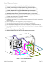
1 Switch off the printer and disconnect the power supply cord.
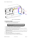
2 Open/remove applicable housing covers.
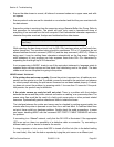
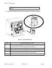
3 Disconnect all wiring harnesses attached to main circuit board (1, Figure 7-1) or daughter
board (2).
Figure 7-1, Circuit Board Replacement
NOTE: Figure 10-1 of the Daigrams & Schematics section provides guidance
on housing cover removal.
I
E
E
E
1
2
8
4
+
R
S
B
O
A
R
D
B
E
L
T
C
O
N
F
I
G
U
R
A
T
I
O
N
1
2
3
4
5
6
7
8
8
8
P
O
W
E
R
B
O
A
R
D