


Section 4: Accessories Installation
M84Pro Service Manual PN 9001111A Page 4-10
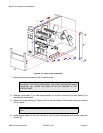
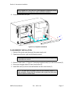
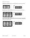
9 Insert a standoff (7) onto each screw (6) from the back side of main circuit board (4).
10 Connect expansion board (8) to the back side of main circuit board (4).
11 Apply a nut (9) to the end of each screw (6). Tighten securely.
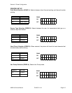
12 Apply a screw (10) into the lower left corner of expansion board (8). Tighten securely.
13 Apply a screw (10) into the front of main circuit board (4) to secure the upper left corner of
expansion board (8). Tighten securely.
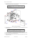
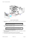
14 Insert main circuit board (4, Figure 4-4a) into the printer and secure using three screws (5)
and two screws (3).
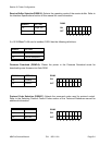
15 Insert interface board (2) into its respective slot to connect with main circuit board (4) and
secure using two screws (1).
16 Restore power, test cycle, and install housing covers.
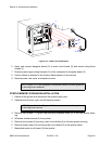
REAL-TIME CLOCK INSTALLATION
The real time clock chip allows the date and time to be maintained in the local printer rather than
using the system clock. It consists of a special clock chip that replaces the EEPROM chip on the
main cicuit board.
1. Switch the printer off and disconnect the power supply cord.
2 Remove the left side housing cover to gain access to the main circuit board.
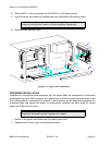
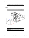
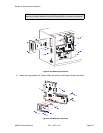
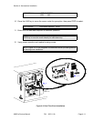
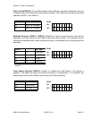
3 Locate and withdraw the EEPROM chip (1, Figure 4-5) from main circuit board (2).
4 Insert clock chip (3) into the vacant connection recepticle (4).
5 Connect the power supply cord.
6 Factory Reset as directed in the Factory Reset section of this manual.
7 Press and hold the LINE key while simultaneously switching the power on.
8 When the printer emits one long beep, release the LINE key.
9 Press the FEED key 11 times to display the prompt to set the calender.
NOTE: Figure 10-1 in the Diagrams & Schematics section provides guidance
on housing cover installation.
CAUTION: IF USING A TOOL TO REMOVE THE EEPROM CHIP, ENSURE
THAT IT IS NOT BEING INSERTED BETWEEN THE RECEPTACLE BOARD
AND THE CIRCUIT BOARD. DESTRUCTION IN THE CIRCUIT BOARD
WILL OCCUR. INSERT THE TOOL BETWEEN THE TWO PIECES OF
BLACK PHENOLIC MATERIAL TO PRY THE CHIP FREE.
LCD DISPLAY: INITIALING ROM V00.00.00.00
LCD DISPLAY: ADVANCED MODE