


Section 7: Replacement Procedures
M84Pro Service Manual PN: 9001111A Page 7-19
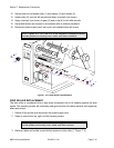
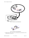
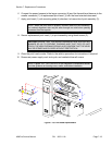
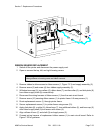
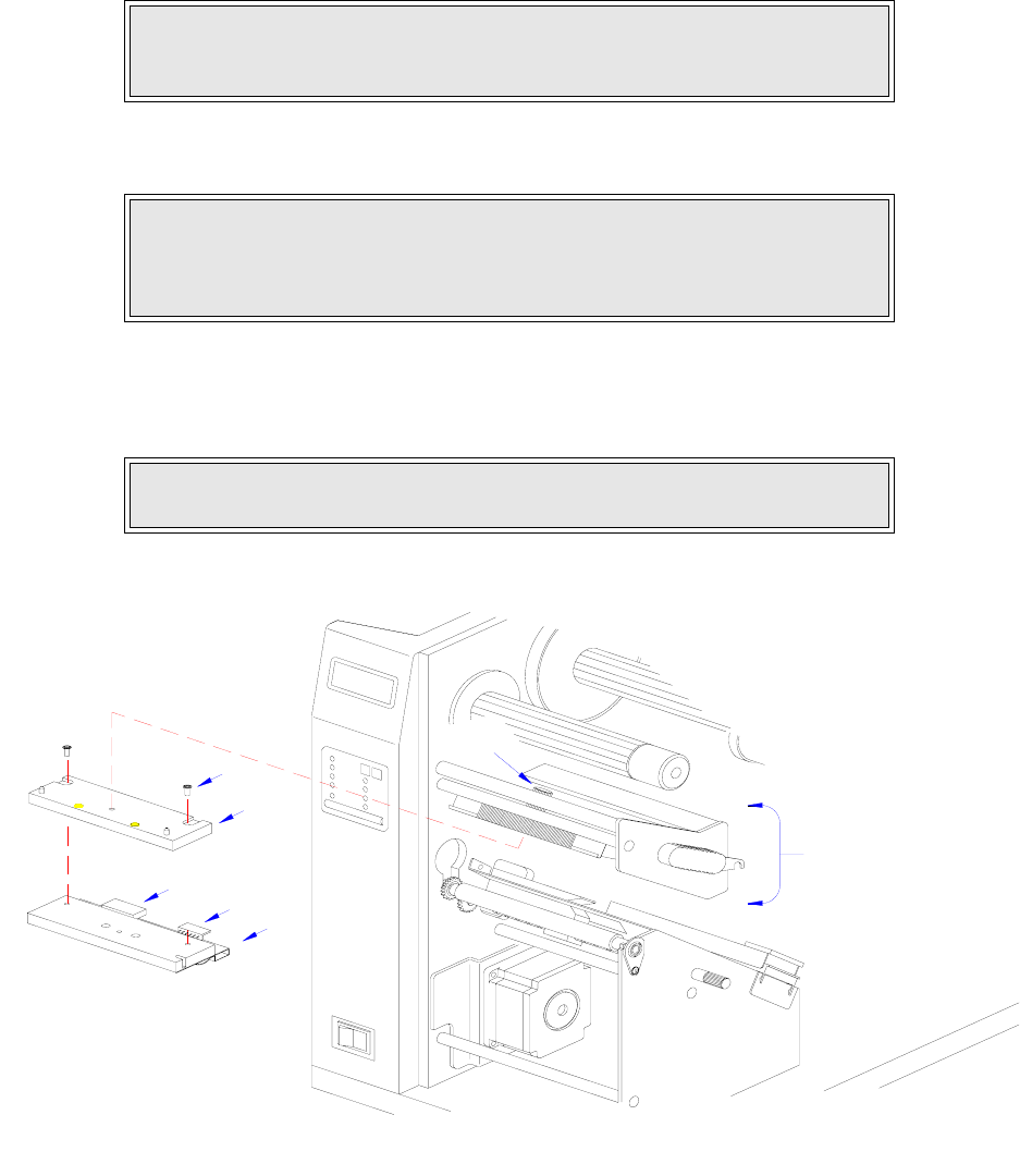
6 Connect the power harness to the larger connector (6) and the thermal head harness to the
smaller connector (7) of replacement print head (1) with the head oriented downward.
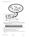
7 Apply print head (1) with mounting plate (4) attached, to lower side of print assembly (3).
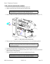
8 Secure replacement print head (1) to print assembly using thumb screw (2).
9 Clear the print head counter. Refer to the relative procedure for instructions if required.
10 Reconnect power supply cord, test cycle, and reattach/close all covers.
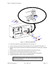
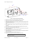
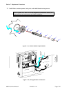
Figure 7-14, Print Head Replacement
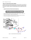
NOTE: When the print head is properly oriented under the print assembly,
two colored alignment dots may be seen through two slots when peering
downward from the top side.
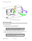
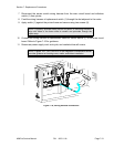
CAUTION: ENSURE THAT THE WIRING HARNESSES ARE ROUTED IN A
MANNER SO AS TO PREVENT PINCHING AND THAT THEY DO NOT
TOUCH THE HEAD OPENING SPRING. ALSO CONFIRM THAT THE HEAD
MAY BE OPENED AND CLOSED WITHOUT RESTRICTION.
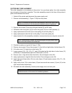
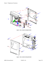
NOTE: Figures 10-1, 10-2, and 10-3 of the Daigrams & Schematics section
provides guidance on housing cover, media, and ribbon installation.
1
3
2
6
7
5
4