


M84Pro Service Manual PN: 9001111A Page 4-1
4
ACCESSORIES INSTALLATION
The following procedures provide in-depth instructions on the installation of all optional
accessories. Each accessory is a purchase option that may not apply to your setup. Refer to the
list below to determine if any are applicable and their installation is required. If not, disregard this
section of the manual and proceed to the next.
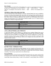
LABEL CUTTER INSTALLATION
This procedure only covers the physical installation of cutter assembly hardware. Refer to other
procedures for configuration, etc.
1 Switch off the printer and disconnect the power supply cord.
2 Open/remove the top, right, and left housing covers.
3 Remove the ribbon and label stock if applicable and leave the print head open.
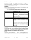
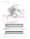
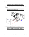
4 Remove screw (1, Figure 4-1a) securing front cover (2) to the printer frame. Lift away front
cover (2).
5 Remove two screws (3) to detach spacer panel (4). Lift away spacer panel (4).
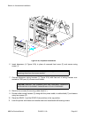
6 Remove four screws (5) from back panel (6) and two screws (7) from side frame bracket (8)
to release the entire print mechanism.
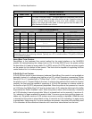
Label Cutter Kit Label dispenser PCMCIA Memory Expansion
Flash Memory Expansion Real Time Clock Interface Module Upgrade
NOTE: Additional relative information may also be found in Figure 10-5,
Accessories & Sensors Location; Figure 10-6, Print Position Reference
Diagram; and Figures 10-12 through 10-15, Operation & Timing Charts of the
Diagrams & Schematics section.
NOTE: Figures 10-1, 10-2, and 10-3 in the Diagrams & Schematics section
provide guidance on housing cover, media, and ribbon removal respectively.
NOTE: The screw is accessible at the rear of the cover on the right side.
Manipulate the cover upward and outward to remove.
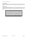
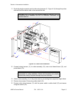
NOTE: The print mechanism will be all that is stainless steel or aluminum.
The print mechanism back plate is vertically arranged and reaches from the
very top down to the base.