


Section 7: Replacement Procedures
M84Pro Service Manual PN 9001111A Page 7-8
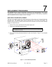
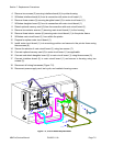
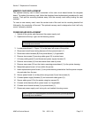
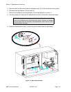
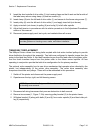
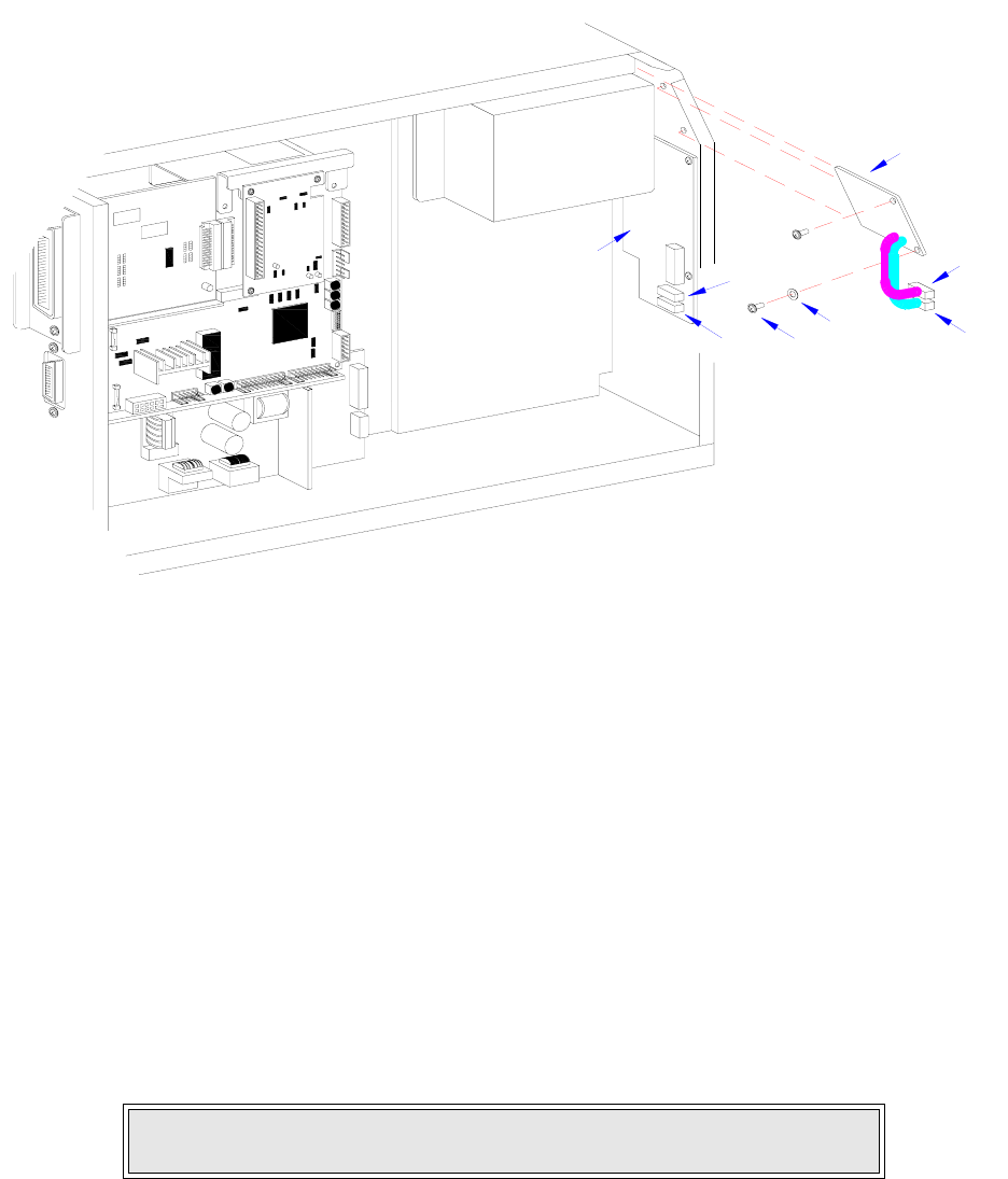
Figure 7-7, LCD Board Replacement
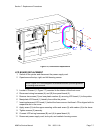
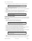
FUSE REPLACEMENT
The M84Pro Printer has three fuses; one is externally accessible and is wired to the power
supply while the other two are located internally and directly connected to the main circuit board.
There is an additional fuse integrated into the optional cutter assembly which is easily accessible
by opening the cutter attachment.
This procedure will address only the power supply and circuit board fuses.
1 Switch off the printer and disconnect the power supply cord.
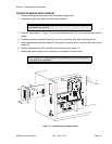
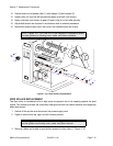
2 Unscrew and remove fuse cap (1, Figure 7-8) and fuse (2) located on the rear printer panel.
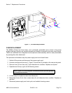
3 Remove fuse (2) from fuse cap (1) and determine its condition. Replace as required.
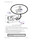
4 Open/remove the top, right, and left housing covers.
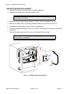
5 Locate fuses (3) located on main circuit board (4).
6 Manipulate fuses (3) for their contact clips (5) and determine their condition. Replace as
required.
7 Reconnect power supply cord, test cycle, and reattach housing covers.
NOTE: Figure 10-1 of the Daigrams & Schematics section provides guidance
on housing cover removal.
P
A
N
E
L
B
O
A
R
D
L
C
D
B
E
L
T
C
O
N
F
I
G
U
R
A
T
IO
N
B
O
A
R
D
1
A
B
4
3
A
B
I
E
E
E
1
2
8
4
+
R
S
B
O
A
R
D
2