


Section 4: Accessories Installation
M84Pro Service Manual PN 9001111A Page 4-8
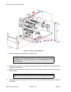
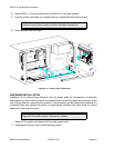
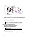
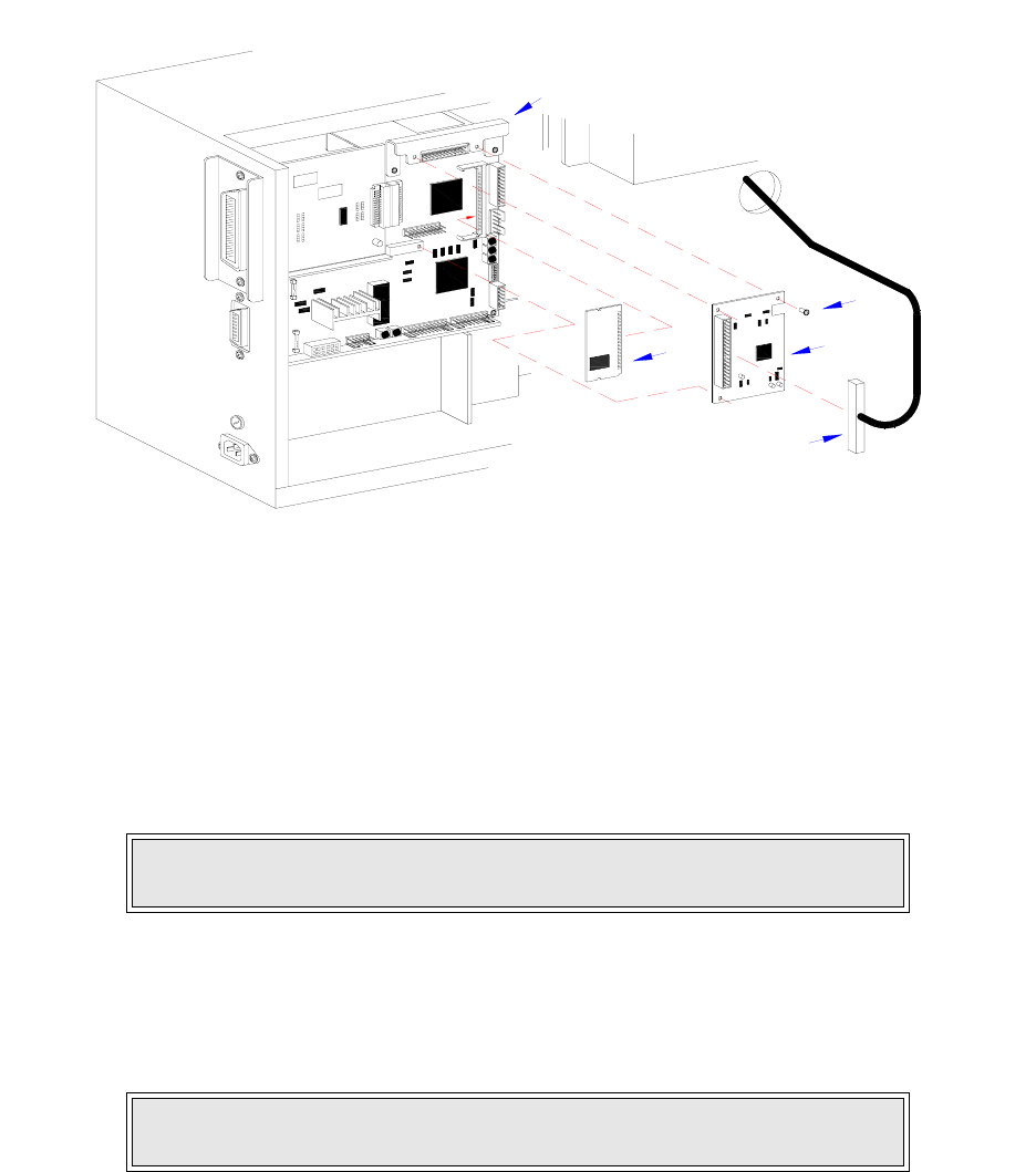
Figure 4-3, Flash Card Installation
6 Apply and connect daughter board (2) to main circuit board (3) and secure using three
screws (1).
7 Ensure power supply wiring harness (5) is fully connected to daughter board (2).
8 Factory Reset as directed in the Factory Reset section of this manual.
9 Restore power, test cycle, and replace covers.
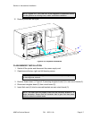
PCMCIA MEMORY EXPANSION INSTALLATION
1 Switch off the printer and disconnect the power supply cord.
2 Open/remove the top, right, and left housing covers.
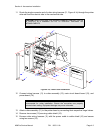
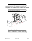
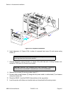
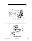
3 Remove two screws (1, Figure 4-4a) securing interface board (2) to the rear printer hous-
ing.
4 Withdraw interface board (2) from printer.
5 Remove two screws (3) securing main circuit board (4) to the rear printer housing.
6 Remove three screws (5) securing main circuit board (4) to the printer frame.
7 Manipulate main circuit board (4) from printer.
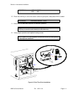
NOTE: Figure 10-1 in the Diagrams & Schematics section provides guidance
on housing cover installation.
NOTE: Figure 10-1 in the Diagrams & Schematics section provides guidance
on housing cover removal.
I
E
E
E
1
2
8
4
+
R
S
B
O
A
R
D
1
2
3
5
4