


Section 7: Replacement Procedures
M84Pro Service Manual PN: 9001111A Page 7-11
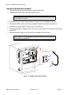
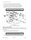
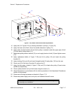
10 Secure heat plate (6) and damper (5) respectively to motor (1) using two screws (4).
11 Reconnect wiring harness (3) to motor (1).
12 Apply motor (1) against the printer frame oriented so that their mounting orifices are
aligned.
13 Apply drive belt to motor spindle and secure to frame using two screws (2).
14 Adjust belt tension on motor (1) as required in accordance with its relative procedure.
15 Reconnect power supply cord, test cycle, and reattach/close all covers.
PLATEN ROLLER REPLACEMENT
The platen roller is considered to be a high wear component due to its treading against the print
media. This treading contact will eventually wear grooves into the rubber material and negatively
effect print output.
1 Switch off the printer and disconnect the power supply cord.
2 Open or remove the front, top, right, and left housing covers.
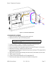
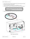
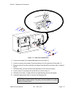
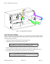
3 Remove ribbon and media to provide free access to platen roller (1, Figure 7-10).
4 Loosen or remove screw (2) securing clamp (3) to right roller spindle.
5 Remove e-clip (4) and the outer belt (not shown) from the left roller spindle and pulley (5).
6 Withdraw pulley (5) from left platen roller spindle and inner belt (not shown).
7 Loosen screw and clamp (not shown) on the left end of roller spindle.
8 Withdraw platen roller (1) along with left and right bushings (6) and gear (7) from the printer.
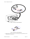
9 Assemble replacement roller as required with gear (7) and bushings (6).
10 Insert the long spindle of platen roller (1) into housing frame so that it protrudes to the drive
side.
11 Allow platen roller (1) to be suspended with its bushings (6) nested on the printer frame.
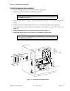
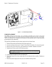
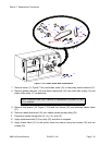
NOTE: The damper and heat sink require mounting in specific orientation.
Regard Figure 6-9 carefully for the correct orientation.
NOTE: Figure 10-1 of the Daigrams & Schematics section provides guidance
on housing cover installation.
NOTE: Figures 10-1, 10-2, and 10-3 of the Daigrams & Schematics section
provide guidance on housing cover, media, and ribbon removal.
NOTE: The bushings must be installed onto the ends of platen roller with
their flanged sides oriented outward. The cog must be installed so its wider
sleeve is oriented outward.