


Section 4: Accessories Installation
M84Pro Service Manual PN: 9001111A Page 4-3
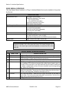
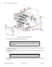
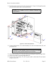
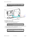
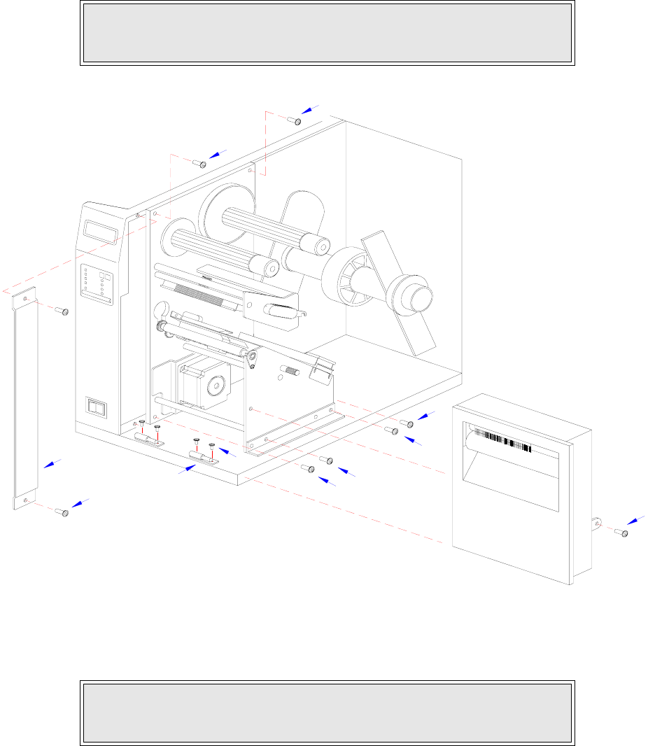
11 Route the single connector end of cutter wiring harness (11, Figure 4-1c) through the printer
side wall from the electric side to the mechanical side.
Figure 4-1b, Label Cutter Installation
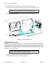
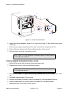
12 Connect wiring harness (11) to cutter assembly (12), main circuit board board (13), and
power board (14).
13 Attach cutter assembly (11) to the printer base by connecting their respective hinge halves.
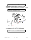
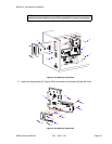
14 Remove two screws (15) securing cable shield (16).
15 Encase cutter wiring harness (11) with the power cable in cable shield (16) and secure
using two screws (15).
CAUTION: WHEN ROUTING THE WIRING HARNESS, ENSURE THAT IS
IS ROUTED IN A MANNER SO AS TO PREVENT PINCHING OR
INTANGLEMENTS.
NOTE: There is one small connector on the wiring harness that will remain
unconnected for cutter installation. Ensure the connectors are properly
oriented when mating. Equipment damage may occur otherwise.
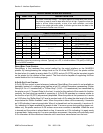
10
5
3
9
7
7
5
5
1
5
4