


Section 7: Replacement Procedures
M84Pro Service Manual PN: 9001111A Page 7-27
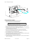
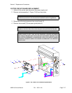
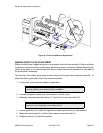
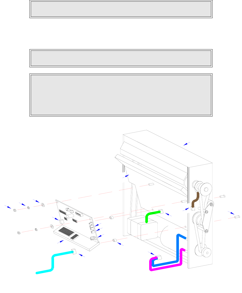
CUTTER CIRCUIT BOARD REPLACEMENT
1 Switch off the printer and disconnect the power supply cord.
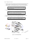
2 Remove cutter assembly (1, Figure 7-24) from the printer.
3 Disconnect all wiring harnesses from circuit board (2).
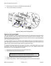
4 Remove two screws (3) from paper guide plate (4).
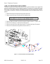
Figure 7-24, Cutter Circuit Board Replacement
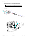
NOTE: If unsure how to remove the cutter assembly, refer to the Label Cutter
Installation procedure in the Accessories Installation section for guidance.
NOTE: The two screws that are to be removed from the paper guide plate are
located on the front side of the cutter along the lower perimeter of the plate.
CAUTION: WHEN THE TWO SCREWS ARE REMOVED FROM THE
PAPER GUIDE PLATE, TWO NYLON SPACERS LOCATED BETWEEN
THE CIRCUIT BOARD AND THE PLATE WILL BE FREED. ENSURE THAT
THE CUTTER ASSEMBLY IS HORIZONTAL WITH THE CIRCUIT BOARD
ORIENTED UPWARD WHEN THE BOARD IS REMOVED TO PREVENT
THEIR LOSS.
1
B
C
8
2
A
7
6
D
5
A
C
B
D
3
2