


16 H9 ASD Installation and Operation Manual
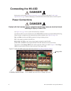
Connecting the H9 ASD
Refer to the section titled Installation Precautions on pg. 4 and the section titled Lead Length
Specifications on pg. 20 before attempting to connect the H9 ASD and the motor to electrical power.
Power Connections
Contact with the 3-phase input or output terminals may cause an electrical shock
resulting in injury or loss of life.
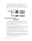
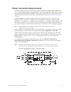
See Figure 20 on pg. 26 for a system I/O connectivity schematic.
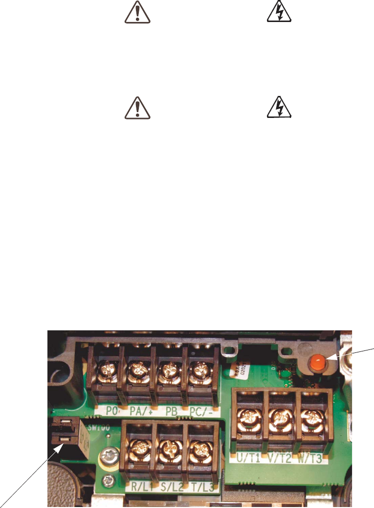
An inductor (DCL) may be connected across the PO and PA/+ terminals to provide additional filtering.
When not used, a jumper must be connected across these terminals (see Figure 20 on pg. 26).
PA/+ and PB are used for the DBR connection if using a braking resistor.
PC/- is the negative terminal of the DC bus.
R/L1, S/L2, and T/L3 are the 3-phase input supply terminals for the H9 ASD.
U/T1, V/T2, and W/T3 are the output terminals of the H9 ASD that connect to the motor.
The location of the Charge LED for the smaller typeform ASD is provided in Figure 2. The Charge
LED is located on the front door of the enclosure of the larger ASDs.
Figure 2. Typical H9 ASD input/output terminals and the Grounding Capacitor Switch.
DANGER
DANGER
Charge LED
Grounding Capacitor Switch — Pull for Small capacitance/Push for Large capacitance.