


24 H9 ASD Installation and Operation Manual
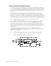
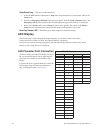
FLC — FLC is the common leg of a single-pole double-throw form C relay. The FL relay is the Fault
Relay by default, but may be programmed to any one of the conditions listed in Table 8 on pg. 241. For
further information on this terminal see F132 and Figure 8.
FLB — The normally-closed leg of the FL relay.
FLA — The normally-open leg of the FL relay.
Note: The FLA, FLB, and FLC contacts are rated at 2A/120 VAC and 2A/30 VDC.
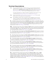
Figure 8. FLA, FLB, and FLC switching contacts shown in the de-energized state.
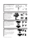
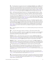
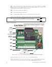
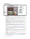
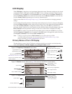
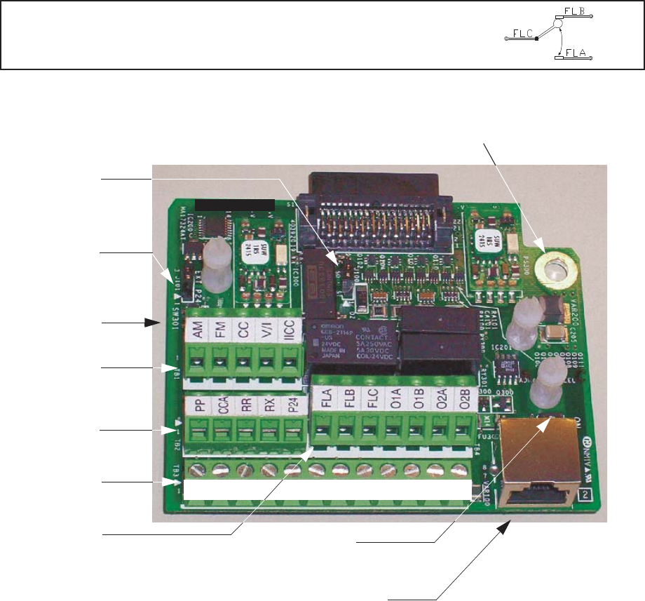
Figure 9. Terminal Board. Sink Source
See the section titled Terminal Descriptions on pg. 22 for terminal descriptions.
See the section titled Cable/Terminal/Torque Specifications on pg. 265 for information on the proper
cable/terminal sizes and torque specifications when making Terminal Board connections.
FLC
FLB
FLA
Note: The relay is shown in the Faulted or de-energized condition.
During normal system operation the relay connection is FLC-
to-FLA.
J101
TB1
TB2
TB3
J100
SW200
TB4
SW301
RES
CC
F
R
S1
S2
S3
S4
CC
ST
FP
+SU
Ensure that the ground screw is securely in place to
prevent arcing, intermittent operation, or system
failure.
1 to 2 = Sink
2 to 3 = Source
1 to 2 = System Supplied
2 to 3 = Ext. Supplied
(24V)
V/I Switch
See Figure 20 on pg. 26 for more information on the Terminal Board connections.
Half/Full Duplex Switch
CAUTION
S4
RS485 4-Wire Communication