


H9 ASD Installation and Operation Manual 237
32 33
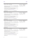
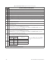
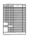
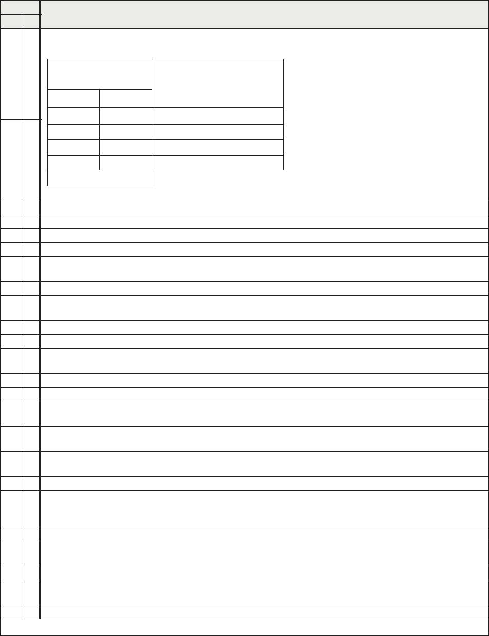
Torque Limit Switching 1/Torque Limit Switching 2 — Activating combinations of discrete input terminals
Torque Limit Switching 1 and 2 allow for the selection of a torque limit switching profile as listed below.
34 35
36 37
PID Off — Turns off PID control.
38 39 Pattern Operation Group 1 — Initiates the Pattern #1 Pattern Run.
40 41 Pattern Operation Group 2 — Initiates the Pattern #2 Pattern Run.
42 43 Pattern Operation Continuation — Initiates a continuation of the last Pattern Run from its stopping point.
44 45
Pattern Operation Trigger — Initiates the first Preset Speed of a Pattern Run and initiates each subsequent
enabled Preset Speed with continued activations.
46 47 External Over-heat — Causes an Over-Heat Trip (OH).
48 49
Local Priority (cancels serial priority) — Overrides any serial control and returns the Command and Frequency
control to the settings of
F003 and F004.
50 51 Hold (3-wire stop) — Decelerates the motor to a stop.
52 53 PID Differentiation/Integration Clear — Clears the PID value.
54 55
PID Forward/Reverse Switching — Toggles the gradient characteristic of the feedback response of the V/I
terminal during PID-controlled operation.
56 57 Forced Continuous Run — Ignore PID control settings for the duration of activation.
58 59 Specified Speed Operation — Runs speed as commanded by the Frequency Mode setting.
60 61
Dwell Signal — Used in conjunction with the Acceleration/Deceleration Suspend function (F349) — suspends the
Accel/Decel function for the duration of the activation.
62 63
Power Failure Synchronized Signal — Activates the Synchronized Accel/Decel function of the Regenerative
Power Ridethrough feature. See
F302 for more information on this terminal setting.
64 65
My Function Run — Activates the configured My Function feature. See F977 for more information on this
parameter.
66 67 Autotuning Signal — Initiates the Autotune function. Set F400 to Autotuning by Input Terminal Signal.
68 69
Speed Gain Switching — Toggles the ASD operating mode from and to Speed Control and Torque Control.
Speed Control operation references parameter settings
F460 and F461. Torque Control operation references
parameter settings F462 and F463.
70 71 Servo Lock — Holds the motor at 0 Hz until a Run command is received.
72 73
Simple Positioning — While operating in the Positioning Control mode, activation initiates the Stop command.
See
F381 for more information on this terminal setting.
74 75 kWH Display Clear — Clears the kWH meter display.
76 77
Trace Back Trigger— Initiates the data Read/Store function of the Trace Selection parameter. See F740 for more
information on this feature.
78 79 Light-Load High-Speed Disable — Terminates the Light-load High-speed operation.
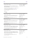
Note: NO/NC = Normally Open/Normally Closed.
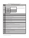
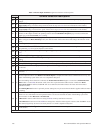
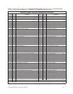
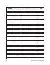
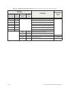
Table 5. Discrete Input Terminal assignment selections and descriptions.
Sel. No.
Terminal Selection Descriptions
NO NC
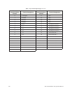
Torque Limit
Switching Terminal
Torque Limit Selection
#1 #2
00 1
01 2
10 3
11 4
1 = Terminal Activated
The 1–4 settings of the torque limit switching
selections are performed at parameters F440 –
F449.