


22 H9 ASD Installation and Operation Manual
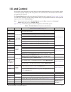
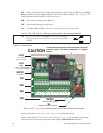
Terminal Descriptions
Note: The programmable terminal assignments may be accessed and changed from their
default settings as mapped on
pg. 46 or via the Direct Access method: Program ⇒
Direct Access ⇒ applicable parameter number. See the section titled Program Mode
Menu Navigation on pg. 46 for the applicable Direct Access parameter numbers.
For further information on terminal assignments and default setting changes, see the
sections titled
Default Setting Changes on pg. 74 and Terminal on pg. 47.
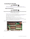
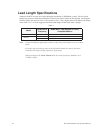
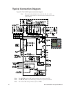
Note: See the section titled Cable/Terminal/Torque Specifications on pg. 265 for the H9
ASD conductor and terminal electrical specifications.
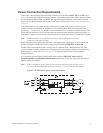
Note: Programmable terminals will not retain their settings indefinitely in the event of a
power loss. Connect an external +24VDC supply to the SU+ terminal to retain the
programmable settings in the event of Control Power loss (see
Figure 20 on pg. 26).
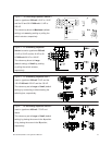
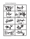
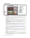
ST — The default setting for this terminal is the Standby mode controller. As the default setting, this
terminal must be activated for normal system operation. The ST terminal is activated by connecting CC
to this terminal (Sink mode). When deactivated the Not Ready to Run icon is displayed on the LCD
screen as shown in
Figure 22. on pg. 31.This input terminal may be programmed to any one of the
functions that are listed in Table 5 on pg. 236 (see F113).
RES — The default setting for this terminal is Reset. The RES terminal is activated by connecting CC
to this terminal (Sink mode). A momentary connection to CC resets the ASD and any fault indications
from the display. Reset is effective when faulted only. This input terminal may be programmed to any
one of the functions that are listed in
Table 5 on pg. 236 (see F114).
F — The default setting for this terminal is the Forward Run Command. The F terminal is activated
by connecting CC to this terminal (Sink mode). This input terminal may be programmed to any one of
the functions that are listed in
Table 5 on pg. 236 (see F111).
R — The default setting for this terminal is the Reverse Run Command. The R terminal is activated
by connecting CC to this terminal (Sink mode). This input terminal may be programmed to any one of
the functions that are listed in
Table 5 on pg. 236 (see F112).
S1 — The default setting for this terminal is the Preset Speed #1 Command. The S1 terminal is
activated by connecting CC to this terminal (Sink mode). This input terminal may be programmed to
any one of the functions that are listed in
Table 5 on pg. 236 (see F115).
S2 — The default setting for this terminal is the Preset Speed #2 Command. The S2 terminal is
activated by connecting CC to this terminal (Sink mode). This input terminal may be programmed to
any one of the functions that are listed in
Table 5 on pg. 236 (see F116).
S3 — The default setting for this terminal is the Preset Speed #3 Command. The S3 terminal is
activated by connecting CC to this terminal (Sink mode). This input terminal may be programmed to
any one of the functions that are listed in
Table 5 on pg. 236 (see F117).
S4 — The default setting for this terminal is the Preset Speed #4 Command. The S4 terminal is
activated by connecting CC to this terminal (Sink mode). This input terminal may be programmed to
any one of the functions that are listed in
Table 5 on pg. 236 (see F118).
RR — The default function assigned to this terminal is the Frequency Mode 1 setting. The RR
terminal accepts a 0 – 10 VDC input signal that is used to carry out the function assigned to this
terminal. This input terminal may be programmed to control the speed or torque of the motor via an
amplitude setting or regulate by setting a limit. The gain and bias of this terminal may be adjusted for
application-specific suitability (see
F210 – F215). See Figure 20 on pg. 26 for an electrical depiction of
the RR terminal. This terminal references CCA.