


238 H9 ASD Installation and Operation Manual
86 87
Binary Write — Writes the status of the discrete input terminals to the control board during binary input speed
control.
88 89
UP/DOWN Frequency (up) — Increases the speed of the motor for the duration of activation until reaching the
Upper Limit setting or increases the speed of the motor in steps (see
F264 for more information on this feature).
90 91
UP/DOWN Frequency (down) — Decreases the speed of the motor for the duration of activation until reaching the
Lower Limit setting or decreases the speed of the motor in steps (see
F264 for more information on this feature).
92 93
UP/DOWN Frequency (clear) — While operating in the Up/Down Frequency speed control mode this terminal
initiates a 0
Hz output command. If operating with an activated UP/DOWN Frequency (up or down) terminal, the
output goes to the Lower Limit (
F013) setting.
98 99
Forward/Reverse — This setting operates in conjunction with another terminal being set to the Run/Stop function.
When configured to Run (Run/Stop to CC), the make or break of this connection to CC changes the direction of the
motor.
100 101 Run/Stop — This terminal enables the motor to run when activated and disables the motor when deactivated.
102 103
Commercial Power/ASD Switching — Initiates the ASD-to-Commercial Power switching function.
See parameter F354 for more information on this feature.
104 105
Frequency Reference Priority Switching — Toggles frequency control to and from the settings of F004 and
F207.
106 107 V/I Terminal Priority — Assigns Speed control to the V/I Terminal and overrides the F004 setting.
108 109
Command Terminal Board Priority — Assigns Command control to the Terminal Board and overrides the F003
setting.
110 111 Edit Enable — Allows for the override of the lockout parameter setting (F700) allowing for parameter editing.
112 113 Control Switching — Toggles the system to and from the speed control and the torque control modes.
122 123
Fast Deceleration — Using dynamic braking (if enabled and supported), stops the motor at the fastest rate allowed
by the load.
124 125
Preliminary Excitation — Applies an excitation current to the motor (holds shaft stationary) for the duration of the
activation.
126 127
Brake Request — Braking Request — Initiates the brake release command. This setting requires that another
discrete input terminal be set to Brake Answerback Input to complete the brake release command and to convey the
status of the braking system to the user or to a dependent subsystem.
Once the braking release function is initiated, the Trouble Internal Timer begins to count down (Trouble Internal
Timer value is set at
F630). Should the count-down timer expire before the brake releases or before the Brake
Answerback Input is returned, fault E-11 will occur. Otherwise, the brake releases the motor and normal motor
operations resume.
The Braking Release function is primarily used at startup; but, may be used when the brake is applied while the motor
is running.
130 131
Brake Answerback Input — Brake Answerback Input — This setting is required when the Braking Request
function is used. The function of this input terminal is to receive the returned the status of the braking system. The
returned status is either Released or Not Released.
If Released is returned within the time setting of F630, normal system function resumes.
If Not Released is returned or if the F630 time setting times out before either signal is returned, then fault E-11 occurs.
The returned signal may also be used to notify the user or control a dependent subsystem.
134 135
Traverse Permission Signal — Enables/Disables the Traverse function. See parameter F980 for more information
on this feature.
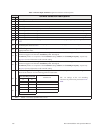
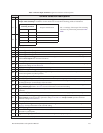
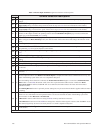
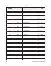
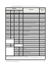
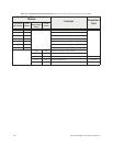
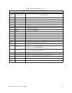
Note: NO/NC = Normally Open/Normally Closed.
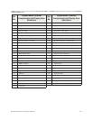
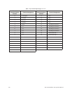
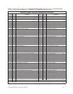
Table 5. Discrete Input Terminal assignment selections and descriptions.
Sel. No.
Terminal Selection Descriptions
NO NC