


H9 ASD Installation and Operation Manual 21
I/O and Control
The H9 ASD can be controlled by several input types and combinations thereof, as well as operate within
a wide range of output frequency and voltage levels. This section discusses the H9 ASD control methods
and supported I/O functions.
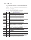
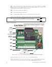
The Terminal Board supports discrete and analog I/O functions and is shown in Figure 9 on pg. 24. Table
2 lists the names, functions, and the settings (default settings of programmable terminals) of the input and
output terminals of the Terminal Board.
Note: To use the input lines of the Terminal Board to provide Run commands the Command
Mode setting must be set to Terminal Block.
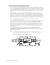
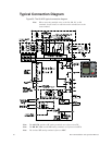
Figure 20 on pg. 26 shows the typical connection diagram for the H9 ASD system.
Table 2. Terminal Board terminal names and functions.
Term. Name Input/Output
Function (Default setting if programmable)
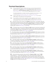
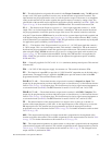
(see Terminal Descriptions on pg. 22)
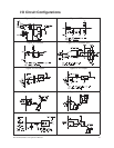
Circuit Config.
ST
Discrete Input
Connect to CC
to activate
(Sink mode).
Standby — Multifunctional programmable discrete input. Activation required
for normal ASD operation.
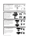
Figure 10 on pg. 25.
RES Reset — Multifunctional programmable discrete input. Resets ASD.
F
Forward — Multifunctional programmable discrete input.
R
Reverse — Multifunctional programmable discrete input.
S1
Preset Speed 1 — Multifunctional programmable discrete input.
S2
Preset Speed 2 — Multifunctional programmable discrete input.
S3
Preset Speed 3 — Multifunctional programmable discrete input.
S4
Preset Speed 4 — Multifunctional programmable discrete input.
O1A/B (OUT1)
Switched
Output
Low Speed — Multifunctional programmable discrete output.
Figure 16 on pg. 25.
O2A/B (OUT2)
Reach Frequency — Multifunctional programmable discrete output.
FLC
Fault relay (common).
Figure 19 on pg. 25.
FLB
Fault relay (N.C.).
FLA
Fault relay (N.O.).
RR
Analog Input
Multifunction programmable analog input (0.0 to 10 volt input — 0 Hz to
Maximum Frequency). Reference CCA.
Figure 11 on pg. 25.
RX
Multifunctional programmable analog input (-10 to +10 VDC input —
0 to ±Maximum Frequency). Reference CCA.
Figure 12 on pg. 25.
V/I
(Select V or I
via SW301)
V — Multifunctional programmable isolated analog voltage input
(0 to 10 VDC input — 0 to Maximum Frequency output). Reference IICC.
Figure 13 on pg. 25.
I — Multifunctional programmable isolated analog current input (0 [4] to
20 mADC input — 0 to Maximum Frequency output). Reference IICC.
AM
Analog
Output
Current output that is proportional to the magnitude of the function assigned
to this terminal (see
Table 6 on pg. 239). Reference CC.
Figure 18 on pg. 25
FM
Current or voltage output that is proportional to the magnitude of the function
assigned to this terminal (see
Table 6 on pg. 239). The output selection is set
at F681. Reference CC.
SU+
DC Input Externally-supplied 24 VDC backup control power (1.1 A max.). Reference CC.
P24
DC Output
24 VDC (200 mA max.) output. Reference CCA. Figure 14 on pg. 25.
PP
10.0 VDC/10 mA voltage source for the external potentiometer. CCA Ref. Figure 15 on pg. 25.
FP Pulsed Output
Frequency Pulse — Multifunctional programmable output pulse train of a
frequency based on the output frequency of the ASD (see
Table 6 on pg. 239).
Figure 17 on pg. 25.
IICC
— Return for the V/I input terminal.
Do Not connect to
Earth Gnd or to
each other.
CCA — Return for the RR, RX, P24, and the PP terminals.
CC
— Return for discrete input terminals and the SU+ input terminal.