


H9 ASD Installation and Operation Manual 269
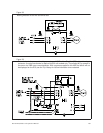
Figure 38.
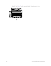
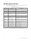
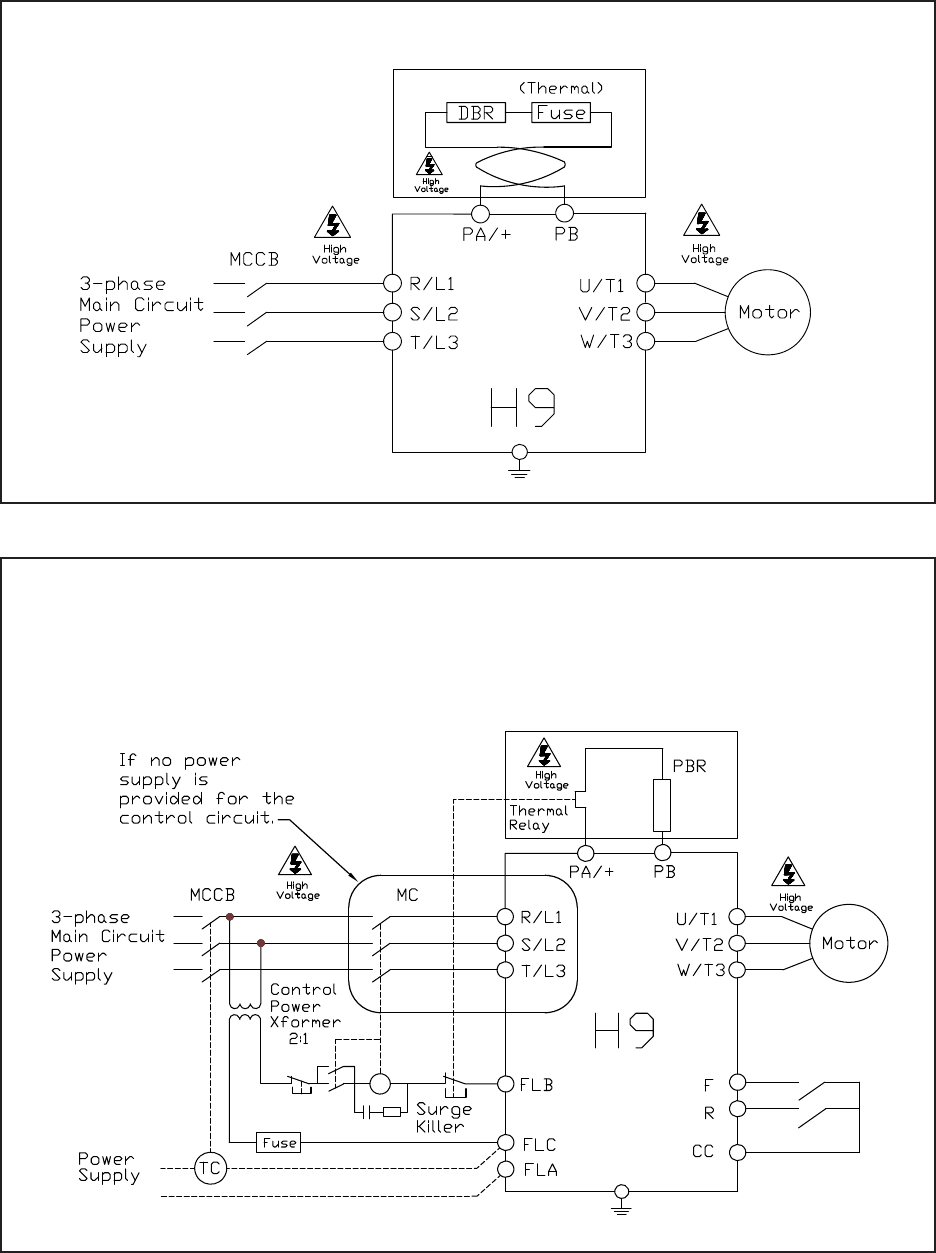
Figure 39.
Braking Resistor circuit with a thermal fuse.
Shown below is the connection diagram using an MCCB with a Trip Coil (TC) in lieu of an input
contactor. A control transformer is required for 400-volt models only. The primary MC is opened in
the event of a DBR over-current detection. With no power supplied to the ASD the failure will not
be displayed on the EOI; see the Trip History for failure information once restarted.