


236 H9 ASD Installation and Operation Manual
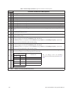
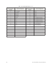
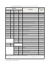
Table 5. Discrete Input Terminal assignment selections and descriptions.
Sel. No.
Terminal Selection Descriptions
NO NC
01Unassigned — No operation.
23Forward — Provides a Forward run command.
45Reverse — Provides a Reverse run command.
67Standby — Enables the Forward and Reverse operation commands.
89Reset — Resets the device and any active faults.
10 11 Preset Speed 1 — Preset Speed 1 is used as the LSB of the 4-bit nibble that is used to select a Preset Speed.
12 13 Preset Speed 2 — Preset Speed 2 is used as the second bit of the 4-bit nibble that is used to select a Preset Speed.
14 15 Preset Speed 3 — Preset Speed 3 is used as the third bit of the 4-bit nibble that is used to select a Preset Speed.
16 17 Preset Speed 4 — Preset Speed 4 is used as the MSB of the 4-bit nibble that is used to select a Preset Speed.
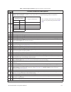
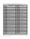
18 19
Jog — This terminal activates a Jog for the duration of the activation. The Jog settings may be configured at F260 –
F262.
20 21
Emergency Off — Terminates the output signal from the drive and may apply a brake if so configured. The braking
method may be selected at F603.
22 23
DC Braking — Upon activation the drive outputs a DC current that is injected into the windings of the motor to
quickly brake the motor.
24 25
A/D 1 — Accel/Decel Switching 1 — Used in conjunction with Accel/Decel Switching 2. Activate or deactivate this
terminal to toggle to and from the Accel/Decel profile 1 through 4.
Accel/Decel profiles are comprised of the Accel/Decel settings, Pattern, and Switching Frequency, respectively.
See F504 for more information on this terminal setting.
26 27
A/D 2 — Accel/Decel Switching 2 — Used in conjunction with Accel/Decel Switching 1. Activate or deactivate this
terminal to toggle to and from the Accel/Decel profile 1 through 4.
Accel/Decel profiles are comprised of the Accel/Decel settings, Pattern, and Switching Frequency, respectively.
See F504 for more information on this terminal setting.
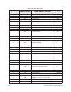
28 29
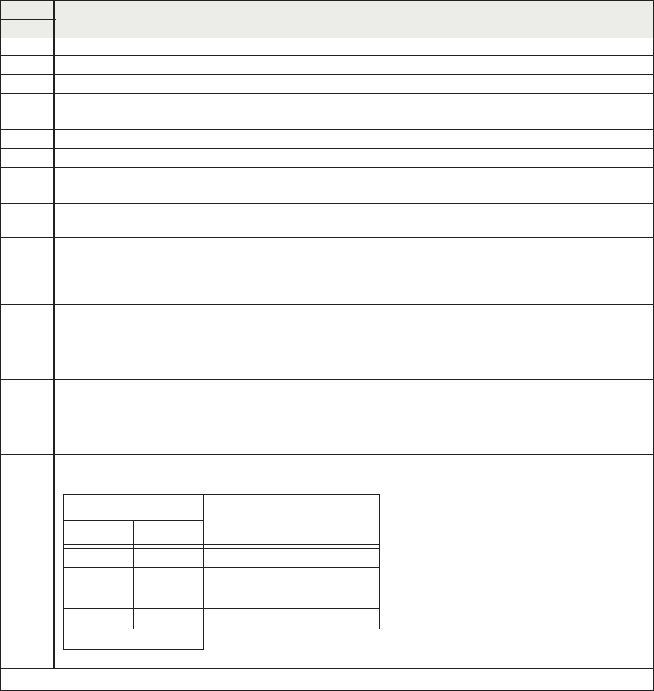
V/f Switching 1/V/f Switching 2 — Activating combinations of discrete input terminals V/f Switching 1 and 2
allow for the selection of a V/f switching profile as listed below.
30 31
Note: NO/NC = Normally Open/Normally Closed.
V/f Switching Terminal
V/f Selection
#1 #2
00 1
01 2
10 3
11 4
1 = Terminal Activated
The 1–4 settings of the V/f Switching
selections are performed at parameters F170 –
F181.