


268 H9 ASD Installation and Operation Manual
Dynamic Braking Resistor Wire/Cable
Specifications
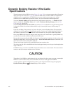
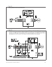
Thermal protection for the DBR circuit (see Figure 38. on pg. 269) or an input contactor that will open the
input 3-phase power circuit (see on pg. 269) to the H9 ASD in the event that a DBR over-temperature
condition occurs is a requirement. If a DBR failure occurs or should a power source over-voltage
condition occur the DBR thermal protection circuitry will prevent hazardous DBR temperatures.
To use the Dynamic Braking function the following requirements must be met — 1) Enable the DBR
function, 2) selected a Resistance Value, and 3) set the Continuous Braking Wattage value at
F304,
F308, and F309, respectively.
Set the Braking Resistance Overload Time at parameter F639 to establish how long the braking resistor
is allowed to sustain the overload condition before a trip is incurred (the factory default setting is 5
seconds).
Light-duty and Heavy-Duty resistors vary from a few ohms to several hundred ohms. The appropriate
resistance size will be typeform-
and application-specific. Contact your Toshiba Sales Representative or
the Toshiba Customer Service Department for more information on your specific DBR requirements.
Heavy duty DBRs should be wired using the same gauge wire as the motor leads. Light duty DBRs may
use one wire size smaller (AWG or kcmil) than the motor leads.
Because the heat generated by the DBR will affect the cooling capacity of the heat sink, the resistor pack
should be mounted above or to the side of the ASD — Never below the ASD. Maintain a minimum of six
inches between the resistor pack and the ASD unit.
The total wire length from the ASD to the DBR should not exceed ten feet.
The wiring from the ASD to the DBR should be twisted approximately two twists per foot throughout the
length of the wire.
If EMI/RFI noise is of concern, the DBR wiring should be three-core screened cable. The screen should
connect to the ASD enclosure and the resistor enclosure.
Though the in-line DBR fuse and the thermal relay are designed into the system to prevent a catastrophic
DBR over-current condition, they are both intended to be used as backup protection ONLY.
A proper typeform-specific and application-specific system setup that includes using the appropriate
Dynamic Braking Resistor
and Overload settings will be required.
CAUTION